Table of Contents
Advertisement
Quick Links
Advertisement
Table of Contents

Related Manuals for GridConnect grid45

Summary of Contents for GridConnect grid45
- Page 1 Evaluation Kit User Guide Revision A.5 August 7, 2023...
- Page 2 Grid Connect and the Grid Connect logo, and combinations thereof are registered trademarks of Grid Connect, Inc. All other product names, company names, logos or other designations mentioned herein are trademarks of their respective owners. GRID45™ and gridconnect© are trademarks of Grid Connect, Inc. Grid Connect Inc. 1630 W. Diehl Rd.
- Page 3 Changes or modifications to this device not explicitly approved by Grid Connect will void the user's authority to operate this device. The information in this guide may change without notice. The manufacturer assumes no responsibility for any errors that may appear in this guide. GRID45™ Evaluation kit User Guide...
-
Page 4: Table Of Contents
Quick Start Documentation ..........................6 Evaluation Kit ..............................6 Contents of the GRID45 Evaluation kit ......................6 Part Numbers for the GRID45 Evaluation Kit ....................7 Operation of the Evaluation Board ......................7 Powering the Evaluation Board ........................... 7 GRID45 Socket ................................ 8 Install the GRID45 Module ........................... -
Page 5: Overview
GRID45 into their product. The GRID45 OEM module is a powerful, Wi-Fi + Ethernet co-processor module that can be used in a wide variety of IIoT applications. It is designed to be a simple, easy to integrate add-on module to an OEMs host processor that provides many of the popular IIoT communication protocols. -
Page 6: Additional Documentation
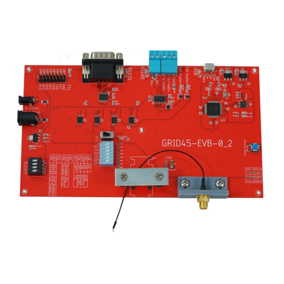
The Evaluation board is easily powered using the provided +5V wall adaptor and provides pin sockets for a GRID45 module to be easily plugged into the evaluation board. The pin sockets also allow the module to be swapped in or out. -
Page 7: Part Numbers For The Grid45 Evaluation Kit
Part Numbers for the GRID45 Evaluation Kit Part Number Description GRID45-EVAL-BD-110 GRID45 Evaluation Kit for 110 Vac US GRID45-EVAL-BD-U GRID45 Evaluation Kit for 110/220 Vac International Plugs Operation of the Evaluation Board Powering the Evaluation Board The evaluation board is supplied with a +5-volt power supply that plugs into a wall outlet. The power supply plugs into the J9 barrel connector on the board. -
Page 8: Grid45 Socket
GRID45 Socket The evaluation board has pin sockets for the GRID45 module that makes it easy to plug in the GRID45 module on the board. The pin sockets allow the module to be interchanged or swapped out as the testing or qualification requires. -
Page 9: Grid45 Connect Dip Switch J10
When installing or removing a GRID45 module from the board, power off this switch. Setting the 3V3 switch (S7) to OFF will isolate power to the GRID45 from the rest of the evaluation board circuit. This is useful when a Direct I/O connection option to the GRID45 module is required. -
Page 10: Reset Button
Reset button There is a reset push button that can be used to reset the GRID45. It is labeled GRID45 Reset. Hold the button for 1 sec to reset the GRID45 Use Cases for the GRID45 Evaluation board The GRID45 Evaluation board is designed to allow 4 application use cases by providing an option for 4 different connection modes to your host device. -
Page 11: Selecting The Connection Mode
There are 2 other switch settings allowed with the J4 DIP switch. 1. DIP switch position 3 controls enabling or disabling all external serial connections to the GRID45. The setting is as follows: Mode Switch pos 3 Labeled 0E... -
Page 12: Direct Connection Option To The Grid45 Module
If a direct connection between the UART of an OEM’s host controller to the pins of the GRID45 module are desired then the GRID45 evaluation board can be modified to support this. To do this the following steps are required: 1. -
Page 13: Example Application Configurations
Host UART Connection to GRID45 through Multiplexor Use this example if you want to connect the UART of the host processor to the GRID45 through the multiplexer circuitry. DIP Switch J10 (6 position DIP switch) 1. -
Page 14: Evaluation Board Schematic
Evaluation board schematic GRID45™ Evaluation kit User Guide... - Page 15 GRID45™ Evaluation kit User Guide...
- Page 16 GRID45™ Evaluation kit User Guide...
- Page 17 GRID45™ Evaluation kit User Guide...
- Page 18 GRID45™ Evaluation kit User Guide...
Need help?
Do you have a question about the grid45 and is the answer not in the manual?
Questions and answers