
Related Manuals for NAL RESEARCH CORPORATION Iridium 9602-NAL

Summary of Contents for NAL RESEARCH CORPORATION Iridium 9602-NAL
- Page 1 451-92695-001C 9602-NAL User Guide Version C February 28, 2024 Copyright © 2024 by NAL Research Corporation 11100 Endeavor Ct., Suite 300 Manassas, Virginia 20109 USA Phone: 703-392-1136 Email: contact@nalresearch.com...
- Page 2 ISCLAIMER AND ONDITION OF This document contains information for the Iridium 9602-NAL Short Burst Data (SBD) Transceiver and accompanying accessories (“Product”), which are provided “as is.” Reasonable effort has been made to make the information in this document reliable and consistent with specifications, test measurements and other information.
- Page 3 9602-NAL User Guide Version C NOTE: This equipment has been tested and found to comply with the limits for a Class A digital device, pursuant to part 15 of the FCC Rules. These limits are designed to provide reasonable protection against harmful interference when the equipment is operated in a commercial environment.
- Page 4 9602-NAL User Guide Version C EFERENCE OCUMENTS The latest revisions of the NAL documents are available from the NAL Research website at https://www.nalresearch.com/support/documentation-downloads/. Reference Title Revision/Date Product Information Model 9602-NAL 2019 AT Commands for Models 9602 (TN2010-111-V1.0) Version 1.0, 2010 SatTerm Software Manual (TN2009-19-V7.0) Version 8.9.7, 2022 Additional Information on DirectIP SBD (TN2007-637-...
-
Page 5: Table Of Contents
9602-NAL User Guide Version C ABLE OF ONTENTS Introduction ......................... 9 Mechanical Interfaces ....................10 Multi-Interface Connector ..................11 RS232 Data Interface (9-Wire Configuration) ..............11 RS232 Data Interface (3-Wire Configuration) ..............12 DC Power Interface ......................12 Power On/Off Control ......................14 DC Supply Indicator Output .................... - Page 6 Appendix F: Mechanical Drawing ..................40 ABLE OF IGURES Figure 1: Iridium 9602-NAL Connectors ..................10 Figure 2: Power Input Settings ...................... 13 Figure 3: Model HRC-24-11 Data/Power Cable Assembly ............14 Figure 4: External ON/OFF Setting for the 9602-NAL ..............15 Figure 5: SYN7391-C Antenna .......................
- Page 7 9602-NAL User Guide Version C LOSSARY AT .......Attention. Two-letter sequence starting a string of terminal commands. The AT is intended to get the terminal’s attention prior to executing a command. BIS ......Bureau of Industry and Security CE .......Conformité Européenne CTS ......Clear To Send DAV ......Data After Voice DC .......Direct Current DCD ......Data Carrier Detect...
- Page 8 9602-NAL User Guide Version C MT-SBD ......Mobile-Terminated Short-Burst Data NIPRNet ......Non-classified Internet Protocol Router Network OFAC ......Office of Foreign Asset Controls PDA ......Personal Digital Assistant PPP ......Point-To-Point Protocol PSTN ......Public Switched Telephone Network PWR ......Power RI ........Ring Indicator RF........Radio Frequency RHCP ......Right-Handed Circular Polarization RTS ......Request To Send RUDICS .......Router-Based Unrestricted Digital Internetworking Connectivity Solution...
-
Page 9: Introduction
9602-NAL User Guide Version C NTRODUCTION This document describes the operational features, configuration settings, and electrical and mechanical interfaces of the 9602-NAL. The 9602-NAL modem is a satellite transceiver comprising an Iridium 9602 transceiver with an extended input voltage range, and only allows Short Burst Data (SBD connectivity to the Iridium satellite network. -
Page 10: Mechanical Interfaces
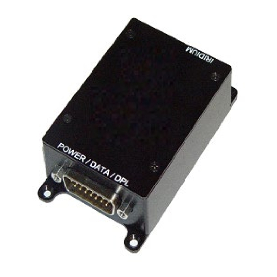
(see section 5). The 9602-NAL is provided with four mounting holes, one at each corner. It is recommended to use 6-32 screws to fasten the modem down. Iridium Antenna Connector Multi-Interface Connector Figure 1: Iridium 9602-NAL Connectors Document Number: 451-92695-001C 10 of 40... -
Page 11: Multi-Interface Connector
9602-NAL User Guide Version C ULTI NTERFACE ONNECTOR The multi-interface connector is a male 15-pin miniature D-Sub type (DB-15 connector) that includes five interfaces—DC power input, power on/off control, RS232 data interface, network availability output, and supply power indicator output. Individual pin assignments are summarized in Table 1. -
Page 12: Rs232 Data Interface (3-Wire Configuration)
9602-NAL User Guide Version C DTE can monitor this pin and use appropriate AT commands to retrieve the MT-SBD message. The 9602-NAL does not support autobaud. Set the baud using the AT+IPR command. The factory-set baud is 19.2 kbps. RS232 D (3-W NTERFACE ONFIGURATION... -
Page 13: Figure 2: Power Input Settings
9602-NAL User Guide Version C when the jumper is on the right pin. Both power pins on the multi-interface connector and their corresponding voltage settings on the jumper must be used for the unit to power up properly. Jumper used to set input voltage range Figure 2: Power Input Settings... -
Page 14: Power On/Off Control
9602-NAL User Guide Version C Figure 3: Model HRC-24-11 Data/Power Cable Assembly Power reset by the 9602-NAL during an SBD session indicates the power source is unable to sustain required peak current demand. OWER ONTROL The 9602-NAL is shipped with hardware set for automatic startup when power is applied, whether the voltage setting is for +5 VDC or for +6.5 VDC to +32 VDC. -
Page 15: Dc Supply Indicator Output
9602-NAL User Guide Version C is in the ‘/’ position. A flathead screw driver can be used to turn the rotary switch to toggle between the two settings. Rotary switch used to set power on/off control Figure 4: External ON/OFF Setting for the 9602-NAL Prior to turning off the 9602-NAL, issue a “flush memory”... -
Page 16: S-Meter Performance
9602-NAL User Guide Version C currently visible, then the update period can be as long as two minutes, depending on how long the lack of satellite visibility existed. This is because the 9602-NAL attempts to conserve power by increasing the ring-search interval while the satellites are not visible. Every time a ring search fails, the time to wait is increased until it reaches a limit at 120 seconds. -
Page 17: Iridium Antenna Connector
9602-NAL User Guide Version C RIDIUM NTENNA ONNECTOR The 9602-NAL uses a single SMA female 50-ohm antenna connector to both transmit and receive. The mating SMA male connectors are readily available from many RF hardware providers. Cable loss between the 9602-NAL and the antenna is critical and must be kept to less than 3 dB at the operating frequency of 1616 to 1626.5 MHz. -
Page 18: Table 3: Custom Antenna Characteristics Required
9602-NAL User Guide Version C If the specific application requires a custom antenna, it must meet the following characteristics in Table 3. Table 3: Custom Antenna Characteristics Required Parameter Value Operating Temperature Range –40°C/+85°C without loss of function Measurement Frequency Range 1616 to 1626.5 MHz Return Loss (Minimum) 9.5 dB (<1.5:1 VSWR) -
Page 19: Gps Pass-Through
In normal operation, this bias would be used to power the LNA inside the active antenna. For the Iridium 9602-NAL, the bias voltage is used to activate an RF switch and enable connection of the GPS port to the antenna port. With external power applied and the 9602-NAL off, the GPS path is still available for use. -
Page 20: Figure 6: Gps Path When 9602-Nal Is Not Transmitting And Gps Is Active
9602-NAL User Guide Version C Figure 6: GPS Path When 9602-NAL is Not Transmitting and GPS is Active Note the following operational points when using the GPS receivers connected to the pass-through GPS SMA connector: • The GPS pass-through path is activated by detecting the presence of a DC voltage on the center pin of the GPS connector. -
Page 21: Configuration Settings
9602-NAL User Guide Version C ONFIGURATION ETTINGS The 9602-NAL allows the DTE to configure the data port communication parameters. The three configuration types are active, factory default, and stored. • The active configuration is the set of parameters currently in use. They can be changed by the DTE individually via specific AT commands. -
Page 22: Modes Of Operations
9602-NAL User Guide Version C ODES OF PERATIONS The RS232 serial interface to a host system DTE is always in one of three modes: • Command mode, • SBD Data mode, • or SBD Session mode. When the data port is in Command mode, AT commands can be entered to control the 9602- NAL. -
Page 23: Hardware Failure Reporting
9602-NAL User Guide Version C ARDWARE AILURE EPORTING If the 9602-NAL detects a hardware problem during initialization, it may not be able to function. Under such case, the 9602-NAL notifies the DTE by issuing an unsolicited result code at the end of initialization: HARDWARE FAILURE: <subsys>,<error>... -
Page 24: Technical Support
9602-NAL User Guide Version C ECHNICAL UPPORT For technical support, please contact us at: Phone: 703-392-1136, x203 Fax: 703-392-6795 Email: contact@nalresearch.com Technical documents are also available to download on NAL Research’s website www.nalresearch.com in the Support > Documentation & Downloads section. Document Number: 451-92695-001C 24 of 40... -
Page 25: Appendix A: Power Consumption Of The 9602-Nal
9602-NAL User Guide Version C A: P 9602-NAL PPENDIX OWER ONSUMPTION OF THE This section provides some insight to the electrical power profile of the 9602-NAL. It does not describe every situation and permutation possible. It is a starting point to continue your own development design. -
Page 26: Figure 7: In-Rush Current Spike During Power-Up (6 Vdc Input)
9602-NAL User Guide Version C In-rush current 3.00 2.25 1.50 0.75 0.00 0.05000 0.05625 0.06250 0.06875 0.07500 Time (Seconds) Figure 7: In-rush Current Spike During Power-up (6 VDC Input) Voltage (DC) Figure 8: In-rush Current Spike During Power-up Document Number: 451-92695-001C 26 of 40... -
Page 27: Figure 9: Current Drawn During Standby
9602-NAL User Guide Version C 0.100 0.075 0.050 0.025 0.000 Voltage (DC) Figure 9: Current Drawn During Standby 0.15 0.12 0.09 0.06 0.03 0.00 Voltage (DC) Figure 10: Current Drawn During SBD Document Number: 451-92695-001C 27 of 40... -
Page 28: Figure 11: Current Drawn During Sleep
9602-NAL User Guide Version C Voltage (DC) Figure 11: Current Drawn During Sleep Document Number: 451-92695-001C 28 of 40... -
Page 29: Appendix B: Standards Compliance
9602-NAL User Guide Version C B: S PPENDIX TANDARDS OMPLIANCE The 9602 transceiver is designed to meet the regulatory requirements for approval for FCC, Canada, and CE, assuming an antenna with a gain of approximately 3 dBi and adequate shielding. The 9602 transceiver is tested to the regulatory and technical certifications shown in the table below. -
Page 30: Appendix C: Export Compliance
9602-NAL User Guide Version C C: E PPENDIX XPORT OMPLIANCE The 9602-NAL is controlled by the export laws and regulations of the United States of America (USA). It is the policy of NAL Research to fully comply with all U.S. export and economic sanction laws and regulations. -
Page 31: Appendix D: The Iridium Network
9602-NAL User Guide Version C D: T PPENDIX RIDIUM ETWORK The Iridium satellite network is owned and operated by Iridium Communications Inc. It is constructed as a constellation of 66 satellites in low-earth orbit, terrestrial gateways, and Iridium Subscriber Units (ISUs). An ISU can either be an Iridium satellite phone or various types of modems. -
Page 32: Iridium Network Data Capabilities
9602-NAL User Guide Version C beams are shut down. The satellite footprint is approximately 4,700 km in diameter. Under each footprint, a satellite is power-limited to approximately 1,100 simultaneous circuits. The Iridium network uses a Time-Division Duplex (TDD) method and transmits and receives in an allotted time window within the frame structure. -
Page 33: Dial-Up Data Service
9602-NAL User Guide Version C Figure 13: Iridium Network Data Capabilities ERVICE Dial-up data service provides connectivity through the Iridium satellite network to another Iridium modem, to the Public Switched Telephone Network (PSTN), to the Defense Switch Network (DSN), to a remote Local Area Network (LAN) (e.g., a corporate network), or to an Internet Service Provider (ISP) at a nominal data rate of 2.4 kilobits per second (kbps). -
Page 34: Figure 14: Pstn Dial-Up Connectivity
9602-NAL User Guide Version C The modem can then be used to call another computer, a remote LAN, or an ISP, as shown in Figure 14. The handshaking and protocols are established between the modems independent of the landline. Antenna Antenna Figure 14: PSTN Dial-up Connectivity The Iridium dial-up data service, as shown in Figure 15, functions in much the same way as the... -
Page 35: Direct Internet Connection
9602-NAL User Guide Version C Figure 15: Iridium Dial-up Data Service IRECT NTERNET ONNECTION The Iridium direct internet service allows users to connect to the internet via the Iridium gateway without having to sign up with an internet service provider. This service utilizes a dedicated Apollo Server at the Iridium gateway, which provides high-speed connectivity to the internet and optimizes server-to-Iridium modem communications. -
Page 36: Short Burst Data
9602-NAL User Guide Version C effective data throughput is achieved through the use of user-transparent data compression. The channel rate is still 2.4 kbps. However, 10 kbps effective throughput can be achieved depending on content (graphics and images result in lower effective throughput). HORT URST SBD is a simple and efficient bidirectional transport capability used to transfer messages with... -
Page 37: Rudics
9602-NAL User Guide Version C SMSC. Unlike standard GSM, the Iridium SMS can only acknowledge that the message was delivered to the SMSC and not the end destination. SMS messages can be sent and received simultaneously while a voice call is in progress. This is possible because SMS messages travel over and above the radio channel using the signaling path, whereas the voice call uses a dedicated “traffic”... -
Page 38: Appendix E: Design Specifications
9602-NAL User Guide Version C E: D PPENDIX ESIGN PECIFICATIONS ECHANICAL PECIFICATIONS Dimensions:..............2.81” x 1.90” x 0.91” (71 mm x 48 mm x 23 mm) Weight (approximate): ..........4.8 oz (136 g) Multi-Interface Connector: ........15-Pin D-Sub Iridium Antenna: ............SMA Enclosure: ..............Aluminum alloy/EMI shielding RF S PECIFICATIONS Operating Frequency: ..........1616 to 1626.5 MHz... -
Page 39: Environmental Specifications
9602-NAL User Guide Version C Receive Current (Average): ........45 mA @ 5 VDC Receive Current (Peak): ..........195 mA @ 5 VDC SBD Message Transfer Current (Average): ....190 mA SBD Message Transfer Power (Average): ....≤ 1.0 W Note: The power requirements apply to DC power measured at the 9602-NAL multi-interface connector input. -
Page 40: Appendix F: Mechanical Drawing
9602-NAL User Guide Version C F: M PPENDIX ECHANICAL RAWING Figure 16: 9602-NAL Mechanical Drawing Document Number: 451-92695-001C 40 of 40...
Need help?
Do you have a question about the Iridium 9602-NAL and is the answer not in the manual?
Questions and answers