Table of Contents
Advertisement
Quick Links
Advertisement
Table of Contents

Related Manuals for VSE.flow RS Series


Summary of Contents for VSE.flow RS Series
- Page 1 Operating instructions for flow meters of the product series “RS“...
-
Page 2: Table Of Contents
TABLE OF CONTENTS Page 1. Important information and legal notices ......... . 3 2. -
Page 3: Important Information And Legal Notices
1. IMPORTANT INFORMATION AND LEGAL NOTICES Dear customer, dear user, This operating instruction for volume sensors of the “RS“ series by VSE Volumentechnik GmbH (VSE) contains informa- tion required to properly install and commission the flow meter for the intended purpose. Any installation, commissioning, operation, maintenance and testing may only be carried out by trained and authorized personnel. -
Page 4: Function Description Of The Rs Flow Meters
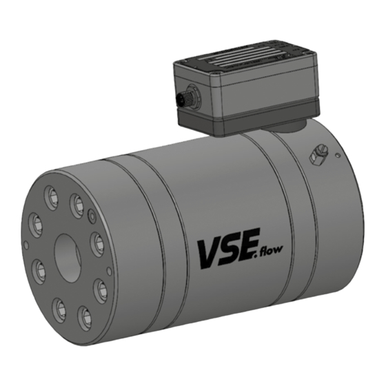
2. FUNCTION DESCRIPTION OF THE RS FLOW METERS RS flow meters measure the flow rate based on the screw pump Sensor System Explanation principle. A pair of rotors fitted precisely into the housing constitutes The non-contact pick-up system consists of two magneto-resistive the measuring element. -
Page 5: General Operating Rrequirements
6. GENERAL OPERATING REQUIREMENTS Before assembly or putting into operation (commissioning), check and verify the following properties and aspects of the respective circumstances of your system to ensure operation is trouble-free, safe, and reliable. 1. The Fluid to be Processed ... -
Page 6: Maximum Operating Pressure
7. MAXIMUM OPERATING PRESSURE Before installing the flow meter, you must check whether the max. ope- operating pressure of 450 bar of the flow meter. Make sure to keep in rating pressure of the system does not exceed the max. permissible mind that peak pressures may occur when operating the system. -
Page 7: Mounting The Flow Meter
10. MOUNTING THE FLOW METER The flow meter should be mounted in an easily accessible location so Non return valve that disassembly to clean the measuring elements is easy. Since flow meters operate in any installation position and flow direction, you can mount it anywhere in your system. -
Page 8: Fluid Filtering
12. FLUID FILTERING Heavily contaminated fluids or foreign matter in the fluid can block, da- and solids are prevented from entering the measuring elements, thus mage, and even destroy the flow meter. In these cases, always install a preventing damage to the flow meter. The required filtering depends on sufficiently large filter in front of the flow meter so that foreign particles the size, bearing, and design of the flow meter. - Page 9 Table 3: Measurement volumes and K-factors RS 40 RS 100 Interpolation Measurement volume K-Factor K-Factor Interpolation Measurement volume K-Factor K-Factor factor (IPF) /Imp] [Imp/l] [Imp/gal.] factor (IPF) /Imp] [Imp/l] [Imp/gal.] 0.31 3226 12212 0.5649 1770 6700 0.155 6452 24424 0.2825 3540 13400 0.1033...
- Page 10 Formula 2: Calculating the max. IPF RS 2500 Interpolation Measurement volume K-Factor K-Factor IPF ≈ f x Vm x 60 IPF1 factor (IPF) /Imp] [Imp/l] [Imp/gal.] x 1000 37.000 18.5000 12.3333 The set IPF may not be larger than the calculated IPF! 9.2500 Interpolation factor 7.4000...
-
Page 11: Settings Of Preamplifier
14. SETTINGS OF THE PREAMPLIFIER The settings are made with the DIP switches located in the lower right alternative IPF from Figure 5 must be set via the three DIP switches. corner of the preamplifier housing (see Figure 4). With these the corre- Alternatively, the DIP switches can also be set to the corresponding sponding interpolation factor IPF (bit 1 to 3) can be selected, the direc- positions and then you can switch between the “normal“... -
Page 12: Pulse Filtering
15. PULSE FILTERING Oscillations in fluid systems manifest themselves through constant for- ments of the rotor measuring unit. The signals at the channel outputs are ward and backward movements of the liquid column, which is also de- also suppressed at the same time until the internal offset is equalized or the initial position of the rotor measuring unit has been reached again tected by the rotor sensors and converted into proportional electronic pulses or edge sequences. -
Page 13: Preamplifier Technical Data
17. PREAMPLIFIER TECHNICAL DATA Scanning sensor Magnetoresistive double measuring bridge Resolution programmable via coding switch 1, 2, 3, 4, 5, 8, 10, 12, 16, 25, 32, 50, 64, 100, 128 Adjustable pulse filtering 8 tooth units Frequency up to 100 kHz Output signals channel A, channel B Channel A and B... -
Page 14: Maintenance, Service Life And Warranty
Important: Only use well-shielded cables for the connection cable, with a wire cross section of ≥ 4 x 0.25 mm². Please make sure that the housing of the round plug is metallic and that it has a connection to the shielding. Important: Please make sure that no extra inductive elements are connected in the power supply of the flow meter, such as contactors, relays, valves etc. -
Page 15: Rs Flow Meter Technical Data
21. RS FLOW METER TECHNICAL DATA Overall size Measuring range K – Factor K – Factor P max. Filtering ) l/min. ccm/rev. ccm/Imp. Imp./l min. Imp./l max. µm max. RS 40 0.04 – 40 (50) 8.37 0.31 3,226 413,000 RS 100 0.50 –... -
Page 16: Rs Flow Meter Flow Characteristics
22. RS FLOW METER FLOW CHARACTERISTICS Size 40 Flow range 0 up to 50 l/min Flow range 0 up to 5 l/min RS 40 (0- 50 l/min) RS 40 (0 - 5 l/min) 21 mm /s 100 mm /s 0,06 0,05 0,04 0,03... -
Page 17: Rs Flow Meter Dimensions
Durchfluss Q Durchfluss Q Size 800 Size Baugröße 800 2500 Flow range 0 up to 1,000 l/min Durchflussbereich 0 bis 1.000 l/min Flow range 0 up to 3,000 l/min Flow range Q Durchfluss Q Flow range Q 23. RS FLOW METER DIMENSIONS RS 40 Vorverstärker Preamplifier... - Page 18 RS 100 Preamplifier Messanschluss Test Port Vorverstärker G1/4 Sensormodul Sensor module Test Port Messanschluss Erdung Earthing G1/4 Ø6 Weight 12 kg Gewicht 12 kg Connection unit Connection unit with sensor Anschlusseinheit Anschlusseinheit mit Sensormodul AR. 100-E.. module AR. 100-E.. AR. 100-E.. AR.
- Page 19 RS 800 Preamplifier Test Port Vorverstärker Messanschluss Sensor module Sensormodul Earthing Erdung Test Port Messanschluss Ring bolt Ringschraube Connection unit with sensor Connection unit Anschlusseinheit Anschlusseinheit mit Sensormodul AR. 800-H.. module AR. 800-H.. AR. 800-H.. AR. 800-H.. Weight 81 kg Gewicht 81 kg deep Connection...
-
Page 20: Rs Flow Meter Type Code
24. RS FLOW METER TYPE CODE RS 100 RS 400 RS 800 RS 2500 Selectable interpolations factor 100; EN-GJS-400-15 (DIN EN 1563)) Stainless steel 1.4305 ( V2A) Stainless steel 1.4571 ( V4A) Pipeline connection Standard Ball bearing Hard metal sleeve bearing with relief Angular contact ball bearing Standard FPM (Viton) Standard... -
Page 21: Plug Assignment
25. PLUG ASSIGNMENT Pin 2 Pin 1 Channel 1 Supply + Volt Supply 0 Volts Channel 2 Pin 3 Pin 4 26. CONNECTION DIAGRAM Flowmeter VSI Evaluating unit (e.g. display) M12-standard + voltage (brown) +8-28V DC channel1 (white) signal- input 1 0 voltage (blue) channel2... -
Page 22: Certificate Of Non-Objection
27. CERTIFICATE OF NON-OBJECTION SAFETY DECLARATION FOR RETURN DELIVERIES (CERTIFICATE OF NON-OBJECTION) Last revised: 10/2021 Please reply to info @ vse-flow.com Flow meters, for which this certificate of conformity has not been completed and signed, cannot be inspected or repaired for safety reasons and will be returned unchecked at your expense. Article number Quantity Reason for return... - Page 23 SAFETY DECLARATION FOR RETURN DELIVERIES (CERTIFICATE OF NON-OBJECTION) Please reply to info @ vse-flow.com The undersigned assures that the above information is correct and complete and the shipping is carried out according to legal regulations. The undersigned is liable for all damages which arise as a result of the non-marked decontamination of the returned flow meter.
- Page 24 VSE Volumentechnik GmbH Hönnestraße 49 58809 Neuenrade / Germany Phone +49 (0) 23 94 / 6 16-30 info@vse-flow.com www.vse-flow.com...
Need help?
Do you have a question about the RS Series and is the answer not in the manual?
Questions and answers