Table of Contents
Advertisement
OPERATING MANUAL
for flow meters of the product line:
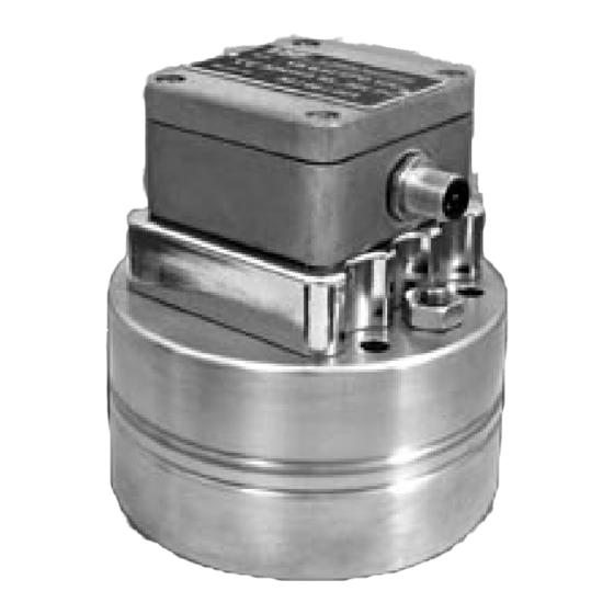
„VSI High Definition Flow Meter"
Grey cast iron version
Stainless steel version
VSE Volumentechnik GmbH
Hönnestrasse 47
58809 Neuenrade Germany
Phone
+ 49 (0)23 94 / 616 30
Fax
+ 49 (0)23 94 / 616 33
e-mail
info@vse-flow.com
Internet www.vse-flow.com
1
Advertisement
Table of Contents

Related Manuals for VSE.flow VSI


Summary of Contents for VSE.flow VSI
- Page 1 OPERATING MANUAL for flow meters of the product line: „VSI High Definition Flow Meter“ Grey cast iron version Stainless steel version VSE Volumentechnik GmbH Hönnestrasse 47 58809 Neuenrade Germany Phone + 49 (0)23 94 / 616 30 + 49 (0)23 94 / 616 33 e-mail info@vse-flow.com...
-
Page 3: Table Of Contents
Technical specifications VSI 0.02 / IPF – VSI 4 / IPF ...... -
Page 4: Function Description Flow Meter
This gives the volume measurement per pulse In flow meters of high resolution (VSI), each tooth is output as a multiple of (Vm) and is defined in cm /pulse. -
Page 5: Maximum Operating Pressure
2. The hydraulic properties of the system Is the max. operating pressure of the system lower than the max. permitted operating pressure of the flow meter? ‹ Is the max. fall of pressure ∆p (on flow meter) below the max. permitted fall of pressure? ‹... -
Page 6: Assembly Of The Flow Meter
flow and at the same time improves measurement accuracy. Block assembly: Flow meters of the “VSI” product line can be mounted directly onto a block or into the pipe line using four screws. Always select large cross sections The flow meter is directly mounted onto a subplate or manifold, extra... -
Page 7: Cleaning And Flushing Of Pipe Lines Before Initial Start-Up
• Cleaning and flushing of pipe lines before initial start-up Before initial start-up of the flow meter, you must flush and clean the whole for the corresponding information. VSE supplies bypass plates for all VSI- system. Contaminated fluid can effect the correct function of the flow meter flow meter sizes. -
Page 8: Flow Meters With High Definition Of Volume Measurement
flanks. A higher resolution is not possible with these pre- amplifiers. Flow meters with interpolation electronics (VSI) output two digital signals But since as high a resolution as possible is necessary for precise and ex- with programmable high resolution that are phase-offset 90° (see Fig. 3). - Page 9 Programmed interpolation factor Volume measurement of the flow meter Example: Flow meter VSI 1/10… max. flow the system can be run on at a maximum ° = 40 l/min = 666.667 ml/sec; IPF = 10; Vm = 1 ml/pulse; f °...
- Page 10 Fig. 3: Interpolation of the volume measurement V At initial start-up of the system, you have to program the volume measu- this value as parameter into your evaluation electronics. rement V * (see Table 4, column 4) in your evaluation electronics as On Table 4 you can view the corresponding volume measurement V * (see parameter value (e.g.
- Page 11 Table 4: Volume measurement and max. frequency at high resolution Flow meter Vol. measurement Interpol. Vol. measure- R-factor* IPF* ment V (pulse/l) (Hz) (ml/pulse) VSI 0.02… 0.02 ml/pulse 2 l/min 1 666.7 Hz 0.02 50 000 1 666.7 (= 2 000 ml/min 0.01 100 000 3 333.3 = 33.33 ml/s)
- Page 12 Flow meter Vol. measurement Interpol. Vol. measure- R-factor* IPF* ment V (pulse/l) (Hz) (ml/pulse) VSI 1… 1 ml/pulse 1 000 80 l/min 1 333.3 Hz 1 333.3 (= 80 000 ml/min 2 000 2 666.7 = 1 333.3 ml/s) 0.33333333 3 000 4 000.0...
-
Page 13: Technical Specifications Of Pre-Amplifier
Example of flow meter “VSI 0,1/10 …” 1. Column : Flow meter, version VSI and size 0.1 VSI 0.1… physical volume measurement V 2. Column: = 0.1 ml/pulse (corresponds to the volume measurement Vm at interpolation factor IPF* = 1) 3. -
Page 14: Plug Assignment Of Pre-Amplifier
• Plug assignment of pre-amplifier Fig. 4 shows the plug assignment of the pre-amplifier. As you can see, this to the pre-amplifier housing and the meter. The cable shielding should al- plug has four pins, the outer four assigned exactly as the ones in standard ways be laid continuously as far as the flow meter and not interrupted in pre-amplifiers. -
Page 15: Sending Back Of Repairs And Sample Devices
If this is not observed, the despatch will be returned, chargeable to obliges industrial corporations to protect their employees and other per- the recipient. sons and environment against harmful effects when handling hazardous • Technical specifications VSI 0.02 / IPF – VSI 4 / IPF Size Measuring range Frequency... -
Page 16: Flow Response Curves Vsi 0.02 - Vsi 4
• Flow response curves VSI 0.02 – VSI 4... -
Page 17: Dimensions Vsi 0.02 - Vsi 4
• Dimensions VSI 0.02 – VSI 4 size øG O-ring Weight 0.02 12.0 11 x 2 0.04 11.5 11 x 2 11 x 2 11 x 2 96.5 11.5 63.5 17.96 x 2.62 12.5 17.96 x 2.62 17.96 x 2.62 36.17 x 2.62... -
Page 18: Dimensions, Subplate Ap. 02 - 4
• Dimensions, subplates AP. 02 - 4 Connection position, side For size Connection øH Thread / depth Weight thread 0.02 G 1/4“ 0.04 G 3/8“ “5 M6 / 12 G 1/2“ G 1/2“ M8 /15 G 3/4“ G 1/2“ G 3/4“ M8 /15 G 1“... -
Page 19: Technical Specifications Vsi 10 / Ipf
• Technical specifications VSI 10 / IPF Size Measuring range Frequency Pulse value R-factor l/min /pulse pulse/litre VSI 10 1.5 … 525 7.50 * IPF … 2625.67 * IPF 3.333 / IPF 300 * IPF Adjustable interpolation factors IPF: 1; 2; 3; 4; 5; 8; 10; 12; 16 Measurement accuracy : up to 0.5 % of measurement value (with viscosity >... -
Page 20: Dimensions Vsi10
• Dimensions VSI10 The dimensions are specified in mm • Dimensions, subplate APG10. APG 10 SG0N / 1 APG 10 SW0N / 1 The dimensions are specified in mm... -
Page 21: Type Key
• Type key Flow meters VSI Type Codes VSI... (interpolation) Interior... -
Page 22: Plug Assignment
Connection plates AP… • Plug assignment... -
Page 23: Pre-Amplifier - Block Wiring Diagram
• Pre-amplifier - block wiring diagram • Connection diagram...
Need help?
Do you have a question about the VSI and is the answer not in the manual?
Questions and answers