Table of Contents
Advertisement
Quick Links
Advertisement
Table of Contents
Troubleshooting

Related Manuals for U-Line U-1224WCB-00A


Summary of Contents for U-Line U-1224WCB-00A
- Page 1 USER GUIDE & SERVICE MANUAL Model: U-1224WCB-00A...
- Page 2 Control Operation - Service Grille / Plinth Installation Control Defaults Door Swing Thermistor Door Stop Defrost Door Adjust Warranty Maintenance Free Standing Kit Cleaning Cleaning Condenser Extended Non-Use Operating Instructions First Use Control Operation Sabbath Mode Airflow and Product Loading U-Line Wine Guide...
-
Page 3: Product Information
® to preserve the right product, in the right place, at the right temperature. Since 2014, U-Line has been part of the Middleby family of brands. All products are designed, engineered, and assembled in Milwaukee, Wisconsin, USA, and select products are available worldwide. -
Page 4: Safety And Warning
USER GUIDE SAFETY • INSTALLATION & INTEGRATION • OPERATING INSTRUCTIONS • MAINTENANCE • SERVICE Safety and Warning DANGER NOTICE This unit contains R600a (Isobutane) which is a Please read all instructions before installing, flammable hydrocarbon. It is safe for regular operating, or servicing the appliance. -
Page 5: Disposal And Recycling
USER GUIDE SAFETY • INSTALLATION & INTEGRATION • OPERATING INSTRUCTIONS • MAINTENANCE • SERVICE Disposal and Recycling DANGER RISK OF CHILD ENTRAPMENT. Before you throw away your old refrigerator or freezer, take off the doors and leave shelves in place so children may not easily climb inside. -
Page 6: Environmental Requirements
USER GUIDE SAFETY • INSTALLATION & INTEGRATION • OPERATING INSTRUCTIONS • MAINTENANCE • SERVICE Environmental Requirements This model is intended for indoor/interior applications only and is not to be used in installations that are open/ exposed to natural elements. This unit is designed to operate between 50°F (10°C) and 100°F (38°C). - Page 7 USER GUIDE Electrical WARNING SHOCK HAZARD — Electrical Grounding Required. Never attempt to repair or perform maintenance on the unit until the electricity has been disconnected. Never remove the round grounding prong from the plug and never use a two-prong grounding adapter.
-
Page 8: Cutout Dimensions
SAFETY • INSTALLATION & INTEGRATION • OPERATING INSTRUCTIONS • MAINTENANCE • SERVICE Cutout Dimensions PREPARE SITE Your U-Line product has been designed for either free- standing or built-in installation. When built-in, your unit does not require additional air space for top, sides, or rear. -
Page 9: Product Dimensions
USER GUIDE SAFETY • INSTALLATION & INTEGRATION • OPERATING INSTRUCTIONS • MAINTENANCE • SERVICE Product Dimensions Not Including Handle 23-1/4" (591 mm) 34-1/8" to 35-1/8" (867 mm to 892 mm) 24" (610 mm) 3-9/16" (91 mm) Product Dimensions 1... -
Page 10: Side-By-Side Installation
USER GUIDE Side-by-Side Installation 3. Place bracket over holes and attach to unit with two screws removed in step 2 using a T-25 Torx driver. Two units may be installed side-by-side. Tighten screws fully. Cutout width for a side-by-side installation is the cutout 4. -
Page 11: Anti-Tip Bracket
USER GUIDE SAFETY • INSTALLATION & INTEGRATION • OPERATING INSTRUCTIONS • MAINTENANCE • SERVICE Anti-Tip Bracket FLOOR MOUNTED ANTI-TIP INSTALLATION 1. Locate two anti-tip brackets included in the kit. 1. Slide unit out so screws on top of unit are easily accessible. - Page 12 USER GUIDE u-line.com SAFETY • INSTALLATION & INTEGRATION • OPERATING INSTRUCTIONS • MAINTENANCE • SERVICE 4. Remove the unit. Using a square, extend center line 5. Place the anti-tip brackets on the floor against the line “B” (see chart below). This line serves as the back drawn for the outer edge.
-
Page 13: General Installation
USER GUIDE SAFETY • INSTALLATION & INTEGRATION • OPERATING INSTRUCTIONS • MAINTENANCE • SERVICE General Installation INSTALLATION 1. Plug in the power/electrical cord. LEVELING INFORMATION 1. Use a level to 2. Gently push the unit into position. Be careful not to confirm the unit is entangle the cord. -
Page 14: Grille - Plinth Installation
USER GUIDE SAFETY • INSTALLATION & INTEGRATION • OPERATING INSTRUCTIONS • MAINTENANCE • SERVICE Grille - Plinth Installation REMOVING AND INSTALLING GRILLE WARNING Disconnect electric power to the unit before removing the grille. When using the unit, the grille (plinth strip/base fascia) must be installed. -
Page 15: Door Swing
USER GUIDE SAFETY • INSTALLATION & INTEGRATION • OPERATING INSTRUCTIONS • MAINTENANCE • SERVICE Door Swing Wall Wall 1/4" Min. 2-1/8" Min. (6 mm) (54 mm) Door Swing Door Swing Units have a zero clearance for the door to open 90°, when installed adjacent to cabinets. - Page 16 3. On 24" models, a second pin is included for the bottom hinge. Repeat steps above for second hinge. Your U-Line unit was shipped to you with the optional 90° pin(s). (Models that are 15" wide include 1 pin. Models NOTE: Threaded pin will be inserted from the bottom.
-
Page 17: Door Alignment And Adjustment
USER GUIDE SAFETY • INSTALLATION & INTEGRATION • OPERATING INSTRUCTIONS • MAINTENANCE • SERVICE Door Adjustments DOOR ALIGNMENT AND ADJUSTMENT Align and adjust the door if it is not level or is not sealing properly. If the door is not sealed, the unit may not cool properly, or excessive frost may form in the interior. - Page 18 USER GUIDE SAFETY • INSTALLATION & INTEGRATION • OPERATING INSTRUCTIONS • MAINTENANCE • SERVICE 3. Remove bottom hinge from cabinet by removing three 4. Tighten three screws. screws. Support the door and hinge assembly and remove it from the cabinet. 5.
- Page 19 USER GUIDE SAFETY • INSTALLATION & INTEGRATION • OPERATING INSTRUCTIONS • MAINTENANCE • SERVICE SHIFTING WINE RACK SPACERS (OPTIONAL) 5. Place the spacer in between the liner and slide. NOTICE Only perform these steps if you require wine rack clearance with a 90° door opening. Doors which are allowed to open past 90°...
-
Page 20: Free Standing Kit
SAFETY • INSTALLATION & INTEGRATION • OPERATING INSTRUCTIONS • MAINTENANCE • SERVICE Free Standing Kit The free standing kit is an optional accessory (ULAFREESTANDS). It is only used when unit is not installed in surrounding cabinetry. Available at u-line.com To install the kit: 1. Remove grille (see GRILLE-PLINTH INSTALLATION section). -
Page 21: First Use
USER GUIDE SAFETY • INSTALLATION & INTEGRATION • OPERATING INSTRUCTIONS • MAINTENANCE • SERVICE First Use All U-Line controls are preset at the factory. Initial startup requires no adjustments. NOTICE U-Line recommends allowing the unit to run overnight before loading with product. -
Page 22: Control Operation
USER GUIDE SAFETY • INSTALLATION & INTEGRATION • OPERATING INSTRUCTIONS • MAINTENANCE • SERVICE Control Operation Alert Up Down Light Power Used CONTROL FUNCTION GUIDE FUNCTION COMMAND DISPLAY/OPTIONS ON/OFF Press and release Unit will immediately turn ON or OFF. Press and release to leave interior Toggle lights Glass door wine and beverage centers only. -
Page 23: Sabbath Mode
The unit will still maintain internal temperatures and set points. View a full list of Star-K certified U-Line units at www.star-k.org. To enable Sabbath Mode: 1. Press (4) and hold for ten seconds and release (the °F/°C symbol will flash briefly at the end of the ten... -
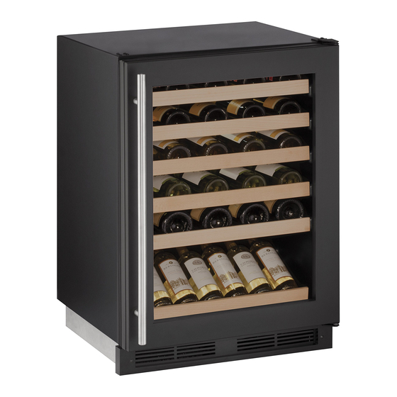
Page 24: Airflow And Product Loading
Anything in direct contact with the evaporator is subject to freezing. When properly loaded, your U-Line unit will store up to 48 (750 ml) bottles of wine. Airflow and Product Loading 1... -
Page 25: U-Line Wine Guide
YOUNG wine OLD wine LIGHT-BODIED wine FULL-BODIED wine Any step back in quality will be noticed. If a fine wine is tasted prior to a lesser wine, many of the fine wine’s subtle qualities may be missed. U-Line Wine Guide 1... - Page 26 Great Bordeaux’s may have as much as a 10-year plateau before fading. Myth 4: Wine color does not change with aging. Truth: As red wines age they get lighter in color while whites get darker. U-Line Wine Guide 2...
-
Page 27: Ideal Wine Storage Considerations
Wines can become flat or tired when voids and vacuums are created inside the wine bottle. In order to create voids and vacuums within a liquid, aggressive motion or shaking of the wine bottle would have to occur. U-Line Wine Guide 3... - Page 28 Approximately 45°F (7°C) Sparkling ® Wine Captain Models - A Touch of Elegance In 1985 U-Line was the first North American appliance manufacturer to develop a residential wine storage unit, ® ® the Wine Captain . Each U-Line Wine Captain...
-
Page 29: Recommended Wine Storage
Specially designed horizontal wine racks properly position the bottles so the wine remains in contact with the cork, which ensures the cork does not become dry. U-Line recommends arranging wine bottles as shown in the illustrations below. Racks 1 through 5:... -
Page 30: Maintenance
USER GUIDE SAFETY • INSTALLATION & INTEGRATION • OPERATING INSTRUCTIONS • • SERVICE MAINTENANCE Cleaning If any surface discoloring or rusting appears, clean it ® ® quickly with Bon-Ami or Barkeepers Friend Cleanser EXTERIOR CLEANING and a nonabrasive cloth. Always clean with the grain. ®... - Page 31 USER GUIDE SAFETY • INSTALLATION & INTEGRATION • OPERATING INSTRUCTIONS • • SERVICE MAINTENANCE High ambient temperature and excessive humidity can also produce frost. CAUTION DO NOT use an ice pick or other sharp instrument to help speed up defrosting. These instruments can puncture the inner lining or damage the cooling unit.
-
Page 32: Cleaning Condenser
USER GUIDE SAFETY • INSTALLATION & INTEGRATION • OPERATING INSTRUCTIONS • MAINTENANCE • SERVICE Cleaning Condenser INTERVAL - EVERY SIX MONTHS To maintain operational efficiency, keep the front grille free of dust and lint, and clean the condenser when necessary. Depending on environmental conditions, more or less frequent cleaning may be necessary. -
Page 33: Wine Rack Installation
USER GUIDE SAFETY • INSTALLATION & INTEGRATION • OPERATING INSTRUCTIONS • MAINTENANCE • SERVICE Wine Rack Installation To remove rack from the cabinet: 1. Remove any bottles stored on the rack. 2. Grasp the end of the rack and gently slide it out until it stops. -
Page 34: Extended Non-Use
If the unit will be exposed to temperatures of 40°F (5°C) or less, the steps above must be followed. For questions regarding winterization, please call U-Line at 414.354.0300. CAUTION Damage caused by freezing temperatures is not covered by the warranty. -
Page 35: Troubleshooting Guide
• Evaporator: Refrigerant flowing through an evaporator may sound like boiling liquid. BEFORE CALLING FOR SERVICE If you think your U-Line product is malfunctioning, read • Condenser Fan: Air moving through a condenser may the CONTROL OPERATION section to clearly understand be heard. -
Page 36: Checking Product Temperature
USER GUIDE SAFETY • INSTALLATION & INTEGRATION • OPERATING INSTRUCTIONS • MAINTENANCE • SERVICE Causes which affect the internal temperatures of Problem Possible Cause and Remedy the cabinet include: Product Is Not Air temperature does not indicate product • Temperature setting. Cold Enough. -
Page 37: Wire Diagram
USER GUIDE SAFETY • INSTALLATION & INTEGRATION • OPERATING INSTRUCTIONS • MAINTENANCE • SERVICE Wire Diagram Wire Diagram 1... -
Page 38: Product Liability
The part that caused the damage must be returned to U-Line in its entirety. The part must be clearly labeled with the serial number of the unit it was removed from, the date, and the servicer who removed the part. -
Page 39: Warranty Claims
• Final Billing – Remodel • Narda (or equivalent) form or submitted online at Noting all of the following on the warranty claim will be www.u-line.com considered proof of purchase, hard copy will not be required: • 60 day submittal deadline from date of completed service •... - Page 40 Parts U-1224WCB-00A Item Description U-Line P/N Anti tip bracket w/screws 80-54221-00 Back panel 80-54204-00 Compressor electricals only 80-54149-00 Compressor w/electricals 80-54150-00 Condenser assembly 80-54264-00 Condenser fan w/screws 80-54014-00 Control Housing 80-54265-00 Display module 80-54493-00 Display rack, btm 80-54318-00 10 Door assembly w/hinges...
- Page 41 Never use a torch on a fully charged refrigeration system. Never substitute U-Line OEM replacement parts or methods of construction. R-600a must be stored and transported in Technician must observe all federal, state and local laws regarding refrigerants.
- Page 42 USER GUIDE SAFETY • INSTALLATION & INTEGRATION • OPERATING INSTRUCTIONS • MAINTENANCE • SERVICE R-600A SPECIFICATIONS/LABELING WARNING R-600a equipped products are labeled (both the unit and the compressor). Only skilled and well trained service technicians permitted to service R-600a equipped products. R-600a is colorless and odorless.
-
Page 43: Leak Detection
USER GUIDE SAFETY • INSTALLATION & INTEGRATION • OPERATING INSTRUCTIONS • MAINTENANCE • SERVICE Evacuate/reclaim via the piecing pliers to ensure the When re-brazing, the system must be purged with dry system is empty of R-600a before any system work is nitrogen and at least one access point open to the performed. - Page 44 USER GUIDE SAFETY • INSTALLATION & INTEGRATION • OPERATING INSTRUCTIONS • MAINTENANCE • SERVICE The low side of the refrigeration system (evaporator, Proper ventilation during service is required. compressor and suction line) must be leak tested with the compressor off (equalized pressure). Never apply a torch to a charged R-600a refrigeration system.
-
Page 45: Refrigeration System Diagnosis Guide
USER GUIDE SAFETY • INSTALLATION & INTEGRATION • OPERATING INSTRUCTIONS • MAINTENANCE • SERVICE System Diagnosis Guide REFRIGERATION SYSTEM DIAGNOSIS GUIDE System Suction Suction Compressor Condenser Capillary Evaporator Wattage Condition Pressure Line Discharge Tube Normal Normal Slightly below Very hot Very hot Warm Cold... -
Page 46: Compressor Specifications
USER GUIDE SAFETY • INSTALLATION & INTEGRATION • OPERATING INSTRUCTIONS • MAINTENANCE • SERVICE Compressor Specifications OVERLOAD PROTECTOR STARTING RELAY DANGER Electrocution can cause death or serious injury. Burns from hot or cold surfaces can cause serious injury. Take precautions when servicing RELAY COVER CAPACITOR this unit. -
Page 47: Troubleshooting - Extended
USER GUIDE SAFETY • INSTALLATION & INTEGRATION • OPERATING INSTRUCTIONS • MAINTENANCE • SERVICE Troubleshooting - Extended Component failure issues can be identified through service mode menu #19, “Component Testing.” Individual SPECIFIC ERRORS AND ISSUES components can be switched on and off to check for both proper function of a specific component and also delivery The technically advanced diagnostic capabilities of the of supply voltage to the components through the relays... -
Page 48: Main Control
USER GUIDE SAFETY • INSTALLATION & INTEGRATION • OPERATING INSTRUCTIONS • MAINTENANCE • SERVICE REFRIGERATION SYSTEM DIAGNOSIS GUIDE System Suction Suction Compressor Condenser Capillary Evaporator Wattage Condition Pressure Line Discharge Tube Normal Normal Slightly below Very hot Very hot Warm Cold Normal room... - Page 49 USER GUIDE SAFETY • INSTALLATION & INTEGRATION • OPERATING INSTRUCTIONS • MAINTENANCE • SERVICE NOTICE Check Voltage Alert Customer No Voltage Frequently toggling the compressor relay could At Wall Outlet Of Power Failure force the compressor into overload. The compressor will automatically deactivate during Voltage an overload and will remain deactivated until the overload switch cools.
-
Page 50: Reed Switch
USER GUIDE SAFETY • INSTALLATION & INTEGRATION • OPERATING INSTRUCTIONS • MAINTENANCE • SERVICE THERMISTOR FAILURE Zone Thermistor If the zone thermistor fails, the unit will continue to operate on a preset time interval of 10 minutes on and 30 minutes off. - Page 51 USER GUIDE SAFETY • INSTALLATION & INTEGRATION • OPERATING INSTRUCTIONS • MAINTENANCE • SERVICE Control Operation - Service UI BUTTON LAYOUT Hidden Button -Accesses Service Menu -No LED Up Button -Increases temperature -Navigates through service menu Down Button -Decreases temperature -Navigates through service menu -LED activated with button activation Light Button...
-
Page 52: Service Mode
USER GUIDE SAFETY • INSTALLATION & INTEGRATION • OPERATING INSTRUCTIONS • MAINTENANCE • SERVICE CONTROL FUNCTION QUICK GUIDE FUNCTION COMMAND DISPLAY/OPTIONS ON/OFF Press and release Unit will immediately turn ON or OFF Press and release to leave interior light Glass door wine captains and beverage centers Toggle lights on for 3 hours only. - Page 53 USER GUIDE SAFETY • INSTALLATION & INTEGRATION • OPERATING INSTRUCTIONS • MAINTENANCE • SERVICE Service Mode Guide Number Service Mode Menu Item To Navigate/Access View thermistor #1 cabinet temp no offsets Use up/down to access and light bulb key to view View thermistor #2 evaporator no offsets Use up/down to access and light bulb key to view View thermistor #3 ambient no offsets...
- Page 54 USER GUIDE SAFETY • INSTALLATION & INTEGRATION • OPERATING INSTRUCTIONS • MAINTENANCE • SERVICE SERVICE MODE GUIDE DEFROST INTERVAL ADJUST — 3 TO 24 HOURS THERMISTOR 1 — TEMPERATURE This will adjust the interval between defrosts from 3 to This will show the pure thermistor reading with no 24 hours.
-
Page 55: Defrost Information
USER GUIDE SAFETY • INSTALLATION & INTEGRATION • OPERATING INSTRUCTIONS • MAINTENANCE • SERVICE INDIVIDUAL COMPONENT TOGGLE RESTORE FACTORY DEFAULTS Relay #2. Will restore all adjustable functions to their factory settings. Relay #3. Will start the ice maker module and forward it through a full harvest cycle Relay #4. -
Page 56: Control Defaults
USER GUIDE SAFETY • INSTALLATION & INTEGRATION • OPERATING INSTRUCTIONS • MAINTENANCE • SERVICE Control Defaults Default Value Fahrenheit/Celsius* °F °C Defrost Duration Minutes Next Defrost Hours Thermistor Four OFFSET** — Thermistor Three OFFSET** — Thermistor Two OFFSET** — Thermistor One OFFSET** —... -
Page 57: Thermistor Failure
USER GUIDE SAFETY • INSTALLATION & INTEGRATION • OPERATING INSTRUCTIONS • MAINTENANCE • SERVICE Thermistors Thermistor Resistance Data Nominal Resistance Temp (F) Temp (C) Thermistors are used for various temperature readings. (OHMS)* Thermistors provide reliable temperature readings using a 169157 resistance which varies based on surrounding 121795 temperatures. - Page 58 USER GUIDE Defrost These units are automatic (cycle) defrost unit will defrost itself when the control/sensor is satisfied of internal temperatures. Defrost mode ends when control/sensor asks for cooling. Defrost 1...
- Page 59 For products installed and used for normal residential use, material cosmetic defects are included in this warranty, with coverage limited to 60 days from the date of original purchase. All service provided by U-Line under the above warranty must be performed by a U-Line factory authorized servicer, unless otherwise specified by U-Line.
Need help?
Do you have a question about the U-1224WCB-00A and is the answer not in the manual?
Questions and answers