Advertisement
Quick Links
Operator's Manual
Power Wave
Register your machine:
www.lincolnelectric.com/register
Authorized Service and Distributor Locator:
www.lincolnelectric.com/locator
Save for future reference
Date Purchased
Code: (ex: 10859)
Serial: (ex: U1060512345)
IM10
| Issue D ate Jul - 2
© Lincoln Global, Inc. All Rights Reserved.
®
For use with machines having Code Numbers:
Need Help? Call 1.888.935.3877
to talk to a Service Representative
Hours of Operation:
8:00 AM to 6:00 PM (ET) Mon. thru Fri.
After hours?
Use "Ask the Experts" at lincolnelectric.com
A Lincoln Service Representative will contact you
no later than the following business day.
For Service outside the USA:
Email: globalservice@lincolnelectric.com
Advertisement

Related Manuals for Lincoln Electric Power Wave 13520

Summary of Contents for Lincoln Electric Power Wave 13520
- Page 1 Operator’s Manual Power Wave ® For use with machines having Code Numbers: Need Help? Call 1.888.935.3877 Register your machine: to talk to a Service Representative www.lincolnelectric.com/register Authorized Service and Distributor Locator: Hours of Operation: www.lincolnelectric.com/locator 8:00 AM to 6:00 PM (ET) Mon. thru Fri. Save for future reference After hours? Use “Ask the Experts”...
- Page 2 THANK YOU FOR SELECTING KEEP YOUR HEAD OUT OF THE FUMES. A QUALITY PRODUCT BY DON’T get too close to the arc. LINCOLN ELEC TRIC. Use corrective lenses if necessary to stay a reasonable distance away from the arc. READ and obey the Safety Data PLEASE EXAMINE CARTON AND EQUIPMENT FOR Sheet (SDS) and the warning label DAMAGE IMMEDIATELY...
- Page 3 P.O. Box 351040, Miami, Florida 33135 or CSA Standard W117.2. A Free copy of “Arc Welding Safety” booklet E205 2.a. Electric current flowing through any conductor is available from the Lincoln Electric Company, 22801 causes localized Electric and Magnetic Fields (EMF). St. Clair Avenue, Cleveland, Ohio 44117-1199.
- Page 4 SAFETY ELECTRIC SHOCK ARC RAYS CAN BURN. CAN KILL. 3.a. The electrode and work (or ground) circuits are 4.a. Use a shield with the proper filter and cover plates to protect your electrically “hot” when the welder is on. Do eyes from sparks and the rays of the arc when welding or not touch these “hot”...
- Page 5 SAFETY WELDING AND CUTTING CYLINDER MAY EXPLODE IF SPARKS CAN CAUSE DAMAGED. FIRE OR EXPLOSION. 7.a. Use only compressed gas cylinders containing the correct shielding gas for the process used 6.a. Remove fire hazards from the welding area. If and properly operating regulators designed for this is not possible, cover them to prevent the welding sparks the gas and pressure used.
- Page 6 EN 60974-10 Electromagnetic Compatibility (EMC) Product Standard for Arc Welding Equipment. It is for use with other Lincoln Electric METHODS OF REDUCING EMISSIONS equipment. It is designed for industrial and professional use.
- Page 7 TABLE OF CONTENTS INSTALLATION .............................SECTION A TECHNICAL SPECIFICATIONS .........................................A-2 INSTALLATION ............................A-3 CONNECTION DIGRAMS ............................A-4 INITIAL CONFIGURATION IO FROM WELDER TO PLC/ROBOT CONTROLLER .....................A-4 .....................A-7 IO FROM PLC/ROBOT CONTROLLER TO WELDER OPERATION ..............................SECTION B SAFETY PRECAUTIONS ......................................B-1 GRAPHIC SYMBOLS ............................B-2 PRODUCT DESCRIPTION...
- Page 8 POWER WAVE INSTALLATION ®...
- Page 9 POWER WAVE INSTALLATION ® Read this entire installation section before you start installation. WARNING...
- Page 10 POWER WAVE INSTALLATION ® CONNECTION DIAGRAM(S), SYSTEM Robot Ethernet / IP ROBOT Automation Customer Supplied CONTROLLER Interface Pendant ArcLink Control K5425-1 Cable K4483-XX Automation Interface Module Ethernet K5479-1 Customer CPU Power Wave Robot Ethernet / IP R450 Customer Supplied K5431-1 Pendant Cable K5456-XX...
- Page 11 POWER WAVE INSTALLATION ® EtherNet/IP Setup Parameters: • VendCode = 346; • VendName = "Lincoln Electric Company"; • ProdType = 43; • ProdTypeStr = "Generic Device (keyable)"; • ProdCode = 26; • MajRev = 1; • MinRev = 1; • ProdName = "LECO Automation Interface";...
- Page 12 POWER WAVE INSTALLATION ® Item Description A True value indicates the Weld Controller detects an Arc. A True value indicates that the welder is testing for work piece contact and detected contact. A True value indicates there is a failure in the gas controller. If a fault occurs during the weld, Power Wave will turn the output off and will not weld until the problem is corrected and the fault is cleared.
- Page 13 POWER WAVE INSTALLATION ® Item Description This bit is used to indicate that the Job Manager has a fault. This includes selecting a job with invalid Workpoint or Trim units, or selecting an invalid Job number. This four bit field returns the state that the welding sequencer is currently in, where 0=Idle (Not welding), 2=Preflow, 3=Strike, 4=Start, 5=Upslope, 6=Weld, 8=Downslope, 9=Crater, 10=Burnback, 11=Postflow, 12=Restrike.
- Page 14 POWER WAVE INSTALLATION ® Cyclic IO from PLC/Robot Controller to Welder Byte Bit 7 Bit 6 Bit 5 Bit 4 Bit 3 Bit 2 Bit 1 Bit 0 IO BIT DESCRIPTION TO WELDER Cyclic IO from PLC/Robot Controller to Welder (Control Bits)
- Page 15 POWER WAVE INSTALLATION ® Item Description This input will cause the power supply to emit only a low current, low voltage, short or zero voltage condition indicating that the wire has touched the work piece. The Touch Sensed output bit is true when touching;...
- Page 16 POWER WAVE OPERATION ® WARNING OR CAUTION EXPLOSION WARNING DANGEROUS VOLTAGE SHOCK HAZARD READ INSTRUCTION MANUAL CUSTOMER NETWORK ROBOT NETWORK PENDANT CONNECTION WELDING POWER SOURCE CONNECTION INPUT POWER DIRECT CURRENT INPUT VOLTAGE INPUT CURRENT...
- Page 17 POWER WAVE OPERATION ®...
- Page 18 POWER WAVE OPERATION ® Job Mode with Parameter Inputs...
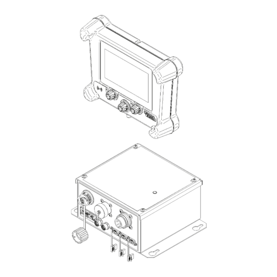
- Page 19 POWER WAVE OPERATION ® TOUCHSCREEN M12 (MODULE) USB PORTS LEFT ADJUSTMENT DIAL RIGHT ADJUSTMENT DIAL CENTER DIAL/PUSHBUTTON...
- Page 20 POWER WAVE OPERATION ®...
- Page 21 POWER WAVE OPERATION ®...
- Page 22 POWER WAVE OPERATION ®...
- Page 23 POWER WAVE OPERATION ®...
- Page 24 POWER WAVE OPERATION ®...
- Page 25 POWER WAVE OPERATION ®...
- Page 26 POWER WAVE OPERATION ®...
- Page 27 POWER WAVE OPERATION ® NOTE: USB device must be formatted as FAT32...
- Page 28 POWER WAVE OPERATION ®...
- Page 29 POWER WAVE OPERATION ®...
- Page 30 POWER WAVE OPERATION ® Sequencer State Description State Purpose Exit Equipment Conditions State IDLE Ready to weld. 1) Trigger On Output: Off Wire: Off Gas: Off PREFLOW Gas purge before welding. 1) Preflow Timer Output: Off 2) Trigger Off Wire: Off Gas: On STRIKE Allow arc to establish.
- Page 31 POWER WAVE OPERATION ® Sequencer State Transitions LGA Weld Sequencer State Transitions Current State Trigger On Trigger Off Arc On Arc Off Time Expires...
- Page 32 POWER WAVE OPERATION ® Sequencer Notes Item Description States The Weld Sequencer supports the Idle, Preflow, Strike, Start, Upslope, Weld, Downslope, Crater, Burnback, Postflow, and Restrike states. State Numbers The state numbers follow the standard Weld Sequencer state numbering – Idle (0), Preflow (2), Strike (3), Start (4), Upslope (5), Weld (6), Downslope (8), Crater (9), Burnback (10), Postflow (11), and Restrike (12) states.
- Page 33 POWER WAVE OPERATION ® Miscellanous Notes Item Description WorkPoint in Amps, Trim These settings should be set to the desired values in the weld control before any jobs in Volts are setup. Once a job(s) is setup, these values must not be changed, else the job will be considered invalid.
- Page 34 ® TROUBLESHOOTING GUIDE Service and Repair should only be performed by Lincoln Electric Factory Trained Personnel. Unauthorized repairs performed on this equipment may result in danger to the technician and machine operator and will invalidate your factory warranty. For your safety and to avoid ELECTRICAL SHOCK, please observe all safety notes and precautions detailed throughout this manual.
- Page 35 POWER WAVE TROUBLESHOOTING ® Status LED Definition LIGHT CONDITION MEANING Automation Interface Module Status Light System OK. Power source is operational, and is communicating normally with all healthy Steady Green peripheral equipment connected to its ArcLink network. Occurs during power up or a system reset, and indicates the module is mapping (identifying) Blinking Green each component in the system.
- Page 36 POWER WAVE TROUBLESHOOTING ® FUNCTION PROBLEMS 1. Incorrect Ethernet/IP Check Anybus communication settings in Advanced Setting communication settings. menu. No Connection to Robot. 1. Incorrect IP address. Check IP address has been set correctly in the Advanced Setting menu. 1. Incorrect M12 connector used Plug pendant cable into pendant connector of module.
- Page 37 POWER WAVE DIAGRAMS ®...
- Page 38 Do not touch electrically live parts or Keep flammable materials away. Wear eye, ear and body protection. WARNING electrode with skin or wet clothing. Insulate yourself from work and ground. Spanish No toque las partes o los electrodos Mantenga el material combustible Protéjase los ojos, los oídos y el AVISO DE bajo carga con la piel o ropa moja-...
- Page 39 Keep your head out of fumes. Turn power off before servicing. Do not operate with panel open or Use ventilation or exhaust to guards off. WARNING remove fumes from breathing zone. Spanish Los humos fuera de la zona de res- Desconectar el cable de ali- No operar con panel abierto o AVISO DE...
- Page 40 WELD FUME CONTROL EQUIPMENT The operation of welding fume control equipment is affected by various factors including proper use and positioning of the equipment, maintenance of the equipment and the specific welding procedure and application involved. Worker exposure level should be checked upon installation and periodically thereafter to be certain it is within applicable OSHA PEL and ACGIH TLV limits.
Need help?
Do you have a question about the Power Wave 13520 and is the answer not in the manual?
Questions and answers