Mack MP7 Service Manual
Hide thumbs
Also See for MP7:
- Body builder instructions (44 pages) ,
- Operator's handbook manual (173 pages)

Related Manuals for Mack MP7


Summary of Contents for Mack MP7
- Page 1 MACK ® DIESEL ENGINE SERVICE MANUAL JULY 2009 (’07 EMISSIONS REGULATIONS) (REVISED) 5-114...
- Page 2 ® MACK MP7 DIESEL ENGINE SERVICE MANUAL ('07 EMISSIONS REGULATIONS) JULY 2009 © MACK TRUCKS, INC. 2009 (REVISED — SUPERSEDES ISSUE DATED JANUARY 2009) ENGINE 5-114...
- Page 3 No part of this publication may be reproduced, stored in a retrieval system, or be transmitted in any form by any means including (but not limited to) electronic, mechanical, photocopying, recording, or otherwise without prior written permission of Mack Trucks, Inc. Page ii...
- Page 4 TABLE OF CONTENTS TABLE OF CONTENTS Page iii...
-
Page 5: Table Of Contents
MP7 ENGINE COMPONENT LOCATION VIEWS ........ - Page 6 TABLE OF CONTENTS MAINTENANCE ..............85 LUBRICATION SYSTEM MAINTENANCE .
- Page 7 TABLE OF CONTENTS EECU and Cooling Plate Removal ..........134 Inlet Manifold Removal .
- Page 8 TABLE OF CONTENTS ROCKER ARM SHAFT BENCH PROCEDURES ........183 Description .
- Page 9 TABLE OF CONTENTS Tandem Pump (Fuel and Power Steering) Installation ......244 Inlet Manifold Installation .
- Page 10 MP7 ENGINE MECHANICAL SPECIFICATIONS ........
- Page 11 NOTES Page x...
-
Page 12: Introduction
INTRODUCTION INTRODUCTION Page 1... -
Page 13: Safety Information
INTRODUCTION SAFETY INFORMATION Advisory Labels Cautionary signal words (Danger-Warning-Caution) may appear in various locations throughout this manual. Information accented by one of these signal words must be observed to minimize the risk of personal injury to service personnel, or the possibility of improper service methods which may damage the vehicle or cause it to be unsafe. -
Page 14: Service Procedures And Tool Usage
INTRODUCTION Service Procedures and Tool Usage Anyone using a service procedure or tool not recommended in this manual must first satisfy himself thoroughly that neither his safety nor vehicle safety will be jeopardized by the service method he selects. Individuals deviating in any manner from the instructions provided assume all risks of consequential personal injury or damage to equipment involved. - Page 15 INTRODUCTION Mack Trucks, Inc. cannot anticipate every Use hoists or jacks to lift or move heavy possible occurrence that may involve a potential objects. hazard. Accidents can be avoided by recognizing NEVER run engine indoors unless exhaust potentially hazardous situations and taking fumes are adequately vented to the outside.
-
Page 16: Explanation Of Numerical Code
GROUP 400 — STEERING, AXLES, WHEELS AND TIRES, DRIVELINE CODE GROUP 500 — BRAKES, AUXILIARY SYSTEMS The organization of MACK service manuals has been upgraded to standardize manual content GROUP 600 — CAB, TRUCK BODY according to a reference system based on component identification. -
Page 17: Conversion Chart
INTRODUCTION CONVERSION CHART Conversion Units Multiply By: Length Calculations Inches (in) Millimeters (mm) 25.40 Inches (in) Centimeters (cm) 2.540 Feet (ft) Centimeters (cm) 30.48 Feet (ft) Meters (m) 0.3048 Yards (yd) Centimeters (cm) 91.44 Yards (yd) Meters (m) 0.9144 Miles Kilometers (km) 1.609 Millimeters (mm) - Page 18 INTRODUCTION Conversion Units Multiply By: Weight Calculations Ounces (oz) Grams (g) 28.5714 Pounds (lb) Kilograms (kg) 0.4536 Pounds (lb) Short Tons (US tons) 0.0005 Pounds (lb) Metric Tons (t) 0.00045 Short Tons (US tons) Pounds (lb) 2000 Short Tons (US tons) Kilograms (kg) 907.18486 Short Tons (US tons)
- Page 19 INTRODUCTION Conversion Units Multiply By: Pressure Calculations Atmospheres (atm) Bars (bar) 1.01325 Atmospheres (atm) Kilopascals (kPa) 101.325 Bars (bar) Atmospheres (atm) 0.98692 Bars (bar) Kilopascals (kPa) Bar (bar) Pounds per Square Inch (psi) 14.5037 Inches of Mercury (in Hg) Kilopascals (kPa) 3.377 Inches of Water (in H2O) Kilopascals (kPa)
-
Page 20: About The Mack Mp7 Engine
INTRODUCTION ABOUT THE MACK MP7 ENGINE [200 EA] The MACK MP7 is a 700 CID (11 liter) engine with unit injectors, a cooled Exhaust Gas Recirculation (EGR) system and the Holset Variable Geometry Turbocharger (VGT). With the addition of a Diesel Particulate Filter (DPF) - Page 21 INTRODUCTION Figure 2 — MP7 Left Side View — Conventional Chassis Page 10...
- Page 22 INTRODUCTION Figure 3 — MP7 Left Side View — Low Cab Forward (LCF) Chassis Exhaust Gas Recirculation — 2007 Variable Geometry Turbocharger There are two configurations of the new EGR The Holset Variable Geometry Turbocharger system. For engines installed on conventional...
- Page 23 MP7. No new transmissions are required, but Special service instructions apply to the camshaft the MP7 will readily adapt to the Allison GEN 4 position sensor. The mounting plate, idler and Series transmissions.
-
Page 24: Service Precautions Summary
Also, the rod caps can be installed only one Preventive maintenance is important to get the way because of the difference in spacing most from the MACK MP7 engine and to ensure between screw holes at each side of the many years of reliable, trouble-free operation. - Page 25 INTRODUCTION 7. Cylinder head installation requires lowering 9. The MP7 engine uses a number of O-rings the head onto the gasket, then pulling the for sealing various fluid joints and tubes. It is head horizontally against the timing gear essential that new O-rings of the correct mounting plate using through screws.
-
Page 26: Visual Identification
VISUAL IDENTIFICATION VISUAL IDENTIFICATION Page 15... -
Page 27: Mp7 Engine Model Identification
VISUAL IDENTIFICATION MP7 ENGINE MODEL NOx, NMHC+NOx and particulate matter emissions IDENTIFICATION Exhaust emission control systems Engine Information Plate A statement concerning the limitation on the fuel to be used in the engine also appears. Code letters under Exhaust Emission Control Systems... -
Page 28: Engine Serial Number Identification
VISUAL IDENTIFICATION Engine Serial Number Identification In addition to the engine information plate on the cylinder head cover, the engine is also identified by the engine serial number stamped into the cylinder block. This serial number is located on the block left side at the front just below the inlet manifold as shown in Figure 5. - Page 29 NOTES Page 18...
-
Page 30: Description And Operation
DESCRIPTION AND OPERATION DESCRIPTION AND OPERATION Page 19... -
Page 31: Mp7 Engine Design Features
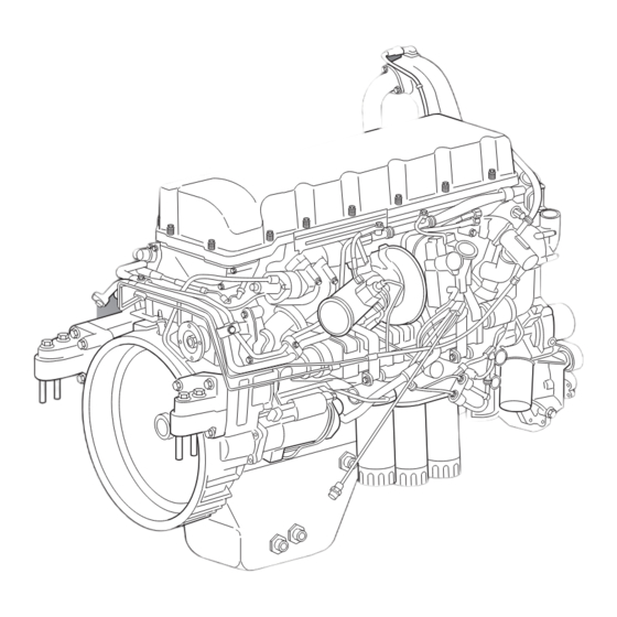
Supports Main features of the cylinder head are: One-piece cast iron Integral thermostat housing Figure 6 — MP7 Engine — Conventional Chassis — Valves angled 12 degrees from normal Right Rear Quarter View (facilitates charge air and exhaust gas flow) - Page 32 DESCRIPTION AND OPERATION CAMSHAFT AND VALVE TRAIN guides have oil seals. All of the valves have double valve springs. Each valve rocker arm The engine has an overhead camshaft, rocker drives two valves via a pinless yoke. Exhaust arm shaft and four valves per cylinder. valve yokes on PowerLeash™...
- Page 33 DESCRIPTION AND OPERATION Figure 9 — Valve Timing Marks 1. Inlet Valve Rocker Arm 6. Rocker Arm Roller (Inlet Valves) 2. Injector Rocker Arm 7. Yoke (Inlet Valves) 3. Exhaust Rocker Arm 8. Camshaft Vibration Damper 4. Camshaft Gear 9. Camshaft Position Sensor Tooth 5.
- Page 34 DESCRIPTION AND OPERATION CYLINDER BLOCK Main bearing caps are made of nodular cast iron processed together with the cylinder block. The cylinder block is made of nodular cast iron. Tapped hole location, cast alignment nipples on For increased cylinder block rigidity and noise the block and caps and sleeves in the tapped and vibration reduction, a 5 mm (0.2 inch) thick holes in the block ensure proper alignment at...
- Page 35 DESCRIPTION AND OPERATION GUIDE PINS In order to facilitate cylinder head installation, there are two guide pins in the cylinder block which match corresponding guide holes in the cylinder head. Figure 11 — Cylinder Head Alignment A. Cylinder Head Locating Holes 1.
- Page 36 DESCRIPTION AND OPERATION CYLINDER HEAD GASKET The cylinder head gasket is made of one piece of sheet steel with vulcanized elastomer seals on oil and coolant conduits. The design of the engine and head gasket requires a unique procedure for installation of the cylinder head.
- Page 37 DESCRIPTION AND OPERATION OIL PAN The oil pan includes an oil level and temperature sensor with connector. The filler tube and dipstick The oil pan is steel with a threaded plug for mounting ports are also components of the oil draining.
- Page 38 DESCRIPTION AND OPERATION CRANKSHAFT The crankshaft is drop forged steel. Bearing surfaces are induction hardened. It has seven Whenever the lower main bearing caps are journals with replaceable bearings. Five installed in the engine block, pay special attention oversized replacement bearing options are to ensure the lower main bearing cap is installed available to accommodate crankshaft regrinding.
- Page 39 DESCRIPTION AND OPERATION PISTONS AND CONNECTING RODS Figure 16 — Piston and Connecting Rod 1. Piston Ring Set 6. Connecting Rod Bolts 2. Wrist Pin Snap Ring 7. Connecting Rod Bearing Cap 3. Piston 8. Upper and Lower Connecting Rod Bearings 4.
- Page 40 DESCRIPTION AND OPERATION Connecting rods are forged steel and are used in The pistons are cooled by oil sprayed upward combination with one-piece Monosteel™ steel from a nozzle in the cylinder block into a vertical pistons. The bearing caps are attached with four duct in the piston.
- Page 41 DESCRIPTION AND OPERATION TIMING GEARS The advantages of this configuration are more precise timing, fewer components and lower The timing gears are located at the rear of the noise levels. The two-piece flywheel housing also engine. All of the gears are helical and nitride serves as the timing gear housing.
- Page 42 DESCRIPTION AND OPERATION DRIVE BELTS Depending on the vehicle, the fan location may be high or low on the fan bracket. Two poly-V belts drive the front engine accessories. The outer, primary belt (10 ribs) drives the coolant pump and fan hub from a pulley on the crankshaft flange nested in the vibration damper.
-
Page 43: Lubrication System
DESCRIPTION AND OPERATION Lubrication System and cooling, to the cylinder head and rocker shaft duct (valve rocker and camshaft) and back to the oil pan. A gear-type pump at the rear of the engine, driven by the crankshaft gear, draws lubricant Two full-flow filters and a by-pass filter maintain from the oil pan and supplies the system. - Page 44 DESCRIPTION AND OPERATION OIL FLOW CONTROL AND FILTRATION Figure 21 — Lubrication System Flow Diagram 1. Gear Pump 7. Full-Flow Filters Overflow Valve 2. Strainer 8. Piston Cooling Opening Valve 3. Safety Valve 9. Piston Cooling Control Valve 4. Oil Distributor Housing 10.
-
Page 45: Crankcase Ventilation
DESCRIPTION AND OPERATION Crankcase Ventilation open spaces are ducted through a pipe that opens to the atmosphere near the bottom of the engine. Lubricant becomes a mist in many areas of the engine as the result of the motion of the parts The crankcase ventilation (CCV) system (e.g., rocker arms, pistons, crankshaft, camshaft separates the oily mist from the gases by... -
Page 46: Fuel System
DESCRIPTION AND OPERATION Fuel System Figure 23 — Fuel System Diagram 1. Fuel Pump 15. Water Discharge Control Switch (Instrument Panel) 2. Fuel Tank and Inlet Tube 16. Electrical Water Drain Valve 3. EECU Cooler 17. Automatic Air Bleed Valve (closes when filter removed) 4. - Page 47 DESCRIPTION AND OPERATION The fuel pump attaches with the power steering Fuel is drawn by the suction side of the fuel pump pump to the flywheel housing at the rear left side. from the fuel tank into the ECU cooling plate and It turns on the same shaft as the power steering enters the fuel filter housing.
- Page 48 DESCRIPTION AND OPERATION FUEL FILTRATION A one-way check valve located in the filter housing prevents fuel from draining back to the Primary and secondary filter elements attach to fuel tank when the engine is shut down. Also the underside of the fuel filter housing. The included in the fuel filter housing is the fuel housing, located at the front lower left side of the pressure sensor just above the secondary filter.
- Page 49 DESCRIPTION AND OPERATION This engine uses double solenoid unit injectors. The fuel pump pressurizes the gallery so that fuel Unlike systems that require separate components rushes into each injector when it opens. Gallery for delivering, pressurizing and injecting, this unit pressure is regulated by a valve that delivers injector combines these functions.
- Page 50 DESCRIPTION AND OPERATION Figure 26 — Unit Injector — Injection and Pressure Drop Phases 1. Pump Plunger 3. Injector Nozzle 2. Fuel Gallery Injection phase (C): The injection phase begins when the fuel valve closes. The camshaft lobe and rocker arm continue to press down on the The dimension by which the injector nozzle pump plunger and injection occurs as the path extends from the head is critical.
-
Page 51: Powerleash™ Engine Brake
DESCRIPTION AND OPERATION PowerLeash™ Engine Brake PowerLeash™ operation depends on all of the following conditions which must exist simultaneously. The engine is equipped with a PowerLeash™ system to assist in slowing the vehicle when Accelerator pedal released necessary. The system includes special: Engine speed above 1100 rpm Wiring harness Clutch pedal released... - Page 52 DESCRIPTION AND OPERATION System Oil Pressure Camshaft Oil Pressure Temperature Pressure Engine Brake Pressure 90–110°C >250 kPa Active 900–2300 220 kPa (194–230°F) (>36 psi) (32 psi) >1100 90–110°C 300–550 kPa Inactive — 80–120 kPa (194–230°F) (44–80 psi) (12–17 psi) >1100 Cold Engine 650 kPa (94 psi)
-
Page 53: Exhaust Gas Recirculation System
4. Cooler Mounting Brackets 2. EGR Cooler Inlet Pipe 5. EGR Crossover Pipe 3. EGR Cooler Figure 31 — MP7 EGR System — Left Side — LCF Chassis 1. EGR Crossover Pipe 6. Intermediate Mixer Inlet Pipe 2. Connecting Hose with Clamps 7. - Page 54 DESCRIPTION AND OPERATION Nitrous oxide (NOx) emission levels increase with temperature is below 65°C (149°F) unless the combustion temperature. The primary function of EECU commands the valve open during the Exhaust Gas Recirculation (EGR) system is automatic cooler cleaning mode. When coolant to cool exhaust gas and send it back to the temperature exceeds 65°C (149°F), engine load combustion chamber to lower the combustion...
-
Page 55: Exhaust Aftertreatment System
DESCRIPTION AND OPERATION EGR COOLER combined with constant fuel temperature maximizes power output and fuel economy and Using engine coolant, the EGR cooler lowers the minimizes noxious emissions. temperature of exhaust gas coming from the EGR valve. The cooler contains a series of vanes that increase cooling efficiency by swirling the hot gas EGR DIAGNOSTICS before it enters the EGR mixing chamber with air... - Page 56 DESCRIPTION AND OPERATION PARTICULATE MATTER Some PM usually remains unconsumed by the heat and collects on the filter. Eventually, the The compounds remaining in the exhaust after residue must be removed by other means. passing through the EGR system contain Remove the filter and physically remove the extremely small particles of soot and ash called remaining material.
- Page 57 DESCRIPTION AND OPERATION ACTIVE REGENERATION For vehicles that are unable to develop or sustain adequate temperature, there is more than one system for supplying sufficient heat. Figure 34 — DPF Catalyzed System Diagram 1. DPF Muffler 10. Inlet Module 2. Temperature Sensors 11.
- Page 58 DESCRIPTION AND OPERATION Figure 35 — DPF Non-Catalyzed System Diagram 1. DPF Muffler 11. Inlet Manifold 2. Muffler and Exhaust Stack 12. Fuel Return 3. Temperature Sensors 13. Fuel Supply 4. Diesel Particulate Filter 14. Air Tank 5. Delta Pressure Differential Sensor 15.
- Page 59 A catalyst works better the higher the vertical back-of-cab (VBOC) DPF unit with muffler temperature up to about 400°C (750°F). Above or a space saver (MACK Cap) DPF unit with this temperature, sulfur can become sulfuric acid. muffler for the conventional chassis. The space...
-
Page 60: Variable Geometry Turbocharger
DESCRIPTION AND OPERATION Variable Geometry Turbocharger The engine is equipped with a variable geometry turbocharger. The turbine housing has a sliding nozzle ring that maintains sufficient back pressure in the exhaust manifold for proper operation of the EGR system. A certain amount of back pressure is required to push the exhaust gases into the pressurized intake air at the EGR mixer. -
Page 61: Cooling System
DESCRIPTION AND OPERATION Cooling System COOLANT PUMP The back of the coolant (water) pump, with its The cooling system incorporates a belt-driven ducts for distributing coolant, is a separate coolant pump integrated into the front of the casting attached to the cylinder block. engine on the right. -
Page 62: Engine Management System
DESCRIPTION AND OPERATION THERMOSTAT Engine Management System This is a piston-type thermostat with piston, bulb, seal and housing in a single assembly. It has ENGINE ELECTRONIC CONTROL UNIT lower pressure drop compared to earlier types. (EECU) The thermostat is mounted on the front of the cylinder head. - Page 63 DESCRIPTION AND OPERATION SENSORS AND ACTUATORS There are sensors on the engine providing for electronic control. The following figures show the locations of the devices on the left and right sides of the engine, respectively. Figure 42 — Engine Sensors, Left Side (< Front) 1.
- Page 64 DESCRIPTION AND OPERATION Figure 43 — Engine Sensors, Right Side (Front >) 1. Camshaft Position 4. Oil Pressure/Temperature 2. Turbo Wheel Speed 5. Engine (Flywheel) Speed 3. Coolant Temperature NOT SHOWN: Coolant Level (in Expansion Tank) Page 53...
-
Page 65: Glossary Of Terms
A microprocessor-based controller mounted on than otherwise possible. the cylinder block. On the MP7 engine, a cooling plate mounts on the surface of the module. A tube Cooled Exhaust Gas Recirculation (CEGR) - Page 66 With the MACK V-MAC IV mixed with the right amount of HC in the air, NOx system, the VECU controls engine speed, cruise...
- Page 67 NOTES Page 56...
-
Page 68: Component Locator
COMPONENT LOCATOR COMPONENT LOCATOR Page 57... -
Page 69: Mp7 Engine Component Location Views
MP7 engine are identified in the illustrations contained in this section. These views do not include all sensor locations. Figure 44 — MACK MP7 Engine, Conventional Chassis — Right Side View 1. EGR Valve 7. By-Pass Oil Filter 2. - Page 70 EGR crossover pipe and the location of the mixer. The mixer appears in the left-side views. Figure 45 — MACK MP7 Engine, Conventional Chassis — Left Side View 1. EGR Mixer 10. Fuel Filter 2.
- Page 71 COMPONENT LOCATOR Figure 46 — MACK MP7 Engine, LCF Chassis — Front View 1. VGT 7. Alternator 2. VGT Control 8. Refrigerant Compressor 3. Thermostat 9. Oil Filter 4. Fan Mounting Bracket 10. Belt Tension Idler 5. EGR Mixer 11. Coolant Pump 6.
- Page 72 COMPONENT LOCATOR Figure 47 — MACK MP7 Engine, LCF Chassis — Left Side View 1. EGR Mixer 8. Fuel Filter 2. EGR Mixer Inlet Tube 9. Refrigerant Compressor 3. CCV Separator 10. Alternator 4. Air Compressor 11. Venturi 5. Power Steering Pump 12.
- Page 73 NOTES Page 62...
-
Page 74: Troubleshooting
TROUBLESHOOTING TROUBLESHOOTING Page 63... -
Page 75: Engine Symptom Diagnosis
Electrical and electronic information is available in the respective engine problems will, for the most part, cause fault codes service manuals and from the MACK Electronic to be set in the V-MAC system. Information System (EIS). EIS is easily accessed with Tech Tool. -
Page 76: Noise And Vibration
TROUBLESHOOTING Noise and Vibration Be sure to discuss noise and vibration issues with the driver. It is important to discover under what conditions these occur. Maybe a test drive will be NORMAL VERSUS ABNORMAL necessary to familiarize yourself with the details of the driver's story. -
Page 77: Engine Checks And Tests
Description Image 9989876 Dial Indicator (Available) 9990105 Sealing Plate for MP7 Cylinder Head 9990106 Sealing Plate for MP7, MP8 and MP10 Cylinder Heads 9990107 Connection Disc for MP7, MP8 and MP10 Cylinder Heads 9990164 Sealing Plate for MP10 Cylinder Head... - Page 78 TROUBLESHOOTING Tool No. Description Image 9996662 Pressure Gauge and Hoses (Available) 9996956 Flywheel Turning Tool for MP7 Engine (Essential) 9999683 Sweep Dial Indicator (Essential) 9999696 Magnetic Stand (Available) 85109036 Cylinder Head Lifting Tool (Essential) Page 67...
- Page 79 TROUBLESHOOTING Tool No. Description Image 88800014 Flywheel Turning Tool for MP8 and MP10 Engines (Essential) 88800031 Camshaft Sensor Depth Gauge (Available) 88800215 Sealing Plate 88800216 EGR Cooler Test Kit J 5347-B Dial Bore Gauge J 42753 Fuel Line Kit J 47364 Cylinder Head Adapter Plate Page 68...
-
Page 80: Camshaft Sensor Depth, Check
1. Remove the plug from the flywheel housing One step below the surface of the and install the appropriate flywheel turning gauge = one shim required. tool, 9996956 (MP7) or 88800014 (MP8 and Both steps above the surface of MP10). the gauge = two shims required. -
Page 81: Camshaft Timing, Check
6 degrees (after TDC) on the flywheel. The dial indicator travel reading should be approximately 1.6 ±0.03 mm (0.06 ±0.01 inch) for MP7 and MP8 or 1.4 ±0.03 mm (0.05 ±0.01 inch) for MP10. This reading indicates a correctly timed camshaft. -
Page 82: Cylinder Head, Pressure Test
(Cylinder Head Removed) Close the stop valve for two minutes. The pressure should not fall. The following procedure applies for MACK MP7, MP8 and MP10 engine cylinder heads. While the 3. Lower the pressure in the cylinder head by procedure is typical, the sealing tools required will adjusting the knob on the pressure gauge be different for each MP engine series. -
Page 83: Cylinder Liner And Piston Wear, Check
TROUBLESHOOTING 4. Attach the cylinder head lifting tool, 9. Lower the pressure in the cylinder head by 85109036, to the cylinder head. adjusting the knob on the pressure gauge control valve. 5. Using a hoist, lower the cylinder head into a container suitable for the pressure test. - Page 84 TROUBLESHOOTING CYLINDER LINER 1. Check the cylinder liner for cracks, paying special attention to the liner flange. The ® standard dye penetrant or Magnaflux method can be used for checking. 2. Measure the cylinder liner wear with a cylinder bore gauge. The original bore size of the cylinder liner can be used as a reference measurement.
-
Page 85: Egr Cooler, Pressure Test
TROUBLESHOOTING EGR Cooler, Pressure Test (Not Applicable for MP8 Euro 3 Engine) 1. Check inside the gas inlet port. If build-up of soot is seen, perform the EGR cooler cleaning procedure before checking for leaks. 2. Lubricate the O-rings on the coolant inlet and outlet port plugs with a suitable O-ring lubricant. -
Page 86: Engine Compression, Test
Engine Compression, Test (on Vehicle) Verify suspected leaks in the cylinder head or Figure 61 — Tie Strap Holding Engine Brake Piston block by pressure testing before replacing these. (MP7 Shown) ® Do not use Magnaflux inspections alone as replacement criteria. - Page 87 Insert the larger end of the oil tube in between the valve and the rocker arm shaft. the rocker shaft. 12. Install the lifting tool, 85109050 (MP7), Make sure the oil seal is in place at the 85109250 (MP8) or 85109035 (MP10), on bottom of the valve assembly.
-
Page 88: Flywheel Housing Runout, Check
1. Clean the flywheel and flywheel housing. 2. Remove the plug from the flywheel housing Figure 64 — Checking Axial Runout and install the appropriate flywheel turning tool, 9996956 (MP7) or 88800014 (MP8, 1. Magnetic Stand, 2. Sweep Dial Indicator, MP10). -
Page 89: Oil Cooler, Pressure Test
TROUBLESHOOTING 5. To check radial runout, position the tip of Oil Cooler, Pressure Test the dial gauge against the inner flange of the 1. Clean the coolant side of the oil cooler with a flywheel housing. Rotate the flywheel and water-soluble degreasing fluid. -
Page 90: Rocker Arm, Check
1. Install the appropriate flywheel turning tool, 4. Set the dial indicator to zero. 9996956 (MP7) or 88800014 (MP8 and 5. Position a pry bar directly under the rocker MP10), and turn the engine until the arm in the shaft area. Pry the rocker arm up camshaft is in a position where the rocker and note the reading on the dial indicator. - Page 91 ROCKER ARM ROLLER BUSHINGS 1. Using the flywheel turning tool, 9996956 (MP7) or 88800014 (MP8 and MP10), turn the engine until the camshaft is in a position where the rocker arm roller being checked is on the base circle of the camshaft lobe.
- Page 92 TROUBLESHOOTING 6. Place a screwdriver between the rocker arm and the roller. Carefully pry the roller out as far as possible and note the value on the dial indicator. Use care when prying or pressing on the roller to avoid damage to the surface of the roller. Figure 73 —...
-
Page 93: Thermostat, Check
TROUBLESHOOTING Thermostat, Check 3. After at least 30 seconds, check that the thermostat is still closed. With the thermostat removed from the engine, 4. Now warm the water to 100°C (212°F). After check its operation as follows: at least 30 seconds at the boiling point, check that the thermostat has opened 1. -
Page 94: Valve Guide Wear, Check
TROUBLESHOOTING Valve Guide Wear, Check WEAR CHECK 1. Remove the oil seals from the valve guides. 2. Mount the cylinder head on a suitable engine stand using the cylinder head adapter plate J 47364. 3. Install a new valve into the guide so that the end of the valve stem is even with the valve guide edge. - Page 95 NOTES Page 84...
-
Page 96: Maintenance
MAINTENANCE MAINTENANCE Page 85... -
Page 97: Lubrication System Maintenance
MAINTENANCE LUBRICATION SYSTEM MAINTENANCE Special Tool Tool No. Description Image 9998487 Oil Filter Wrench (Available) Oil Level Check When checking oil levels, the vehicle must be parked on level ground. Components must be filled to the correct level. DO NOT OVERFILL. The best time to check oil level is while the engine is COLD (prior to starting at the beginning of the work day, or after the vehicle has sat... -
Page 98: Oil And Filter Change Procedure
MAINTENANCE Oil and Filter Change Procedure [219 EV] Figure 79 — Oil Filters and Valve Housing 1. EGR Valve 6. Full-Flow Oil Filters 2. VGT 7. By-Pass Oil Filter 3. EGR Mixer 8. EGR Cooler 4. EGR Crossover Pipe 9. Starter 5. -
Page 99: Crankcase Ventilation System
3. Remove the separator and attempt to turn the turbine manually. If it does not turn easily, replace the separator. Use of anything other than genuine MACK filters 4. If the turbine turns easily, inspect the oil jet may cause damage and may void the engine nozzle. -
Page 100: Fuel Filter Replacement
MAINTENANCE FUEL FILTER REPLACEMENT FUEL FILTER REPLACEMENT Fuel Filter Change Because of ice buildup or fuel waxing which can [231 BA] clog fuel filters, it may be necessary during extremely cold weather to reduce the time or mileage interval between fuel filter changes. FILTER DESCRIPTION Be careful to prevent foreign matter of any kind Two filters ensure that clean, waterless fuel... - Page 101 MAINTENANCE Full-Flow Filter Replacement To replace the full-flow filter: There is a new-style pre-filter with a 1. Make sure the filter casing is thoroughly stepped-down diameter at the bottom of the filter. cleaned. If not already done, wash the area The earlier-style filter has straight sides with a around the filter mounting adapter with a larger bottom diameter which requires an adapter...
-
Page 102: Cooling System Maintenance
MAINTENANCE COOLING SYSTEM MAINTENANCE Special Tool Tool No. Description Image J 48061 Coolant Filter Wrench (Available) Coolant Drain Outlets REMOVE AND REPLACE 1. Close the shut-off valve on the coolant pump Extra outlets provide convenient drain sites for housing. use during maintenance and other procedures involving coolant. -
Page 103: Exhaust Aftertreatment System Maintenance
MAINTENANCE EXHAUST AFTERTREATMENT SYSTEM MAINTENANCE Special Tools Tool No. Description Image 9996049 Coolant Drain Hose (Available) 85111327 VBOC DPF Support Stand DBT2V700 Coolant Extractor/Injector Page 92... -
Page 104: Diesel Particulate Filter
MAINTENANCE Diesel Particulate Filter 4. Remove the lower exhaust V-band clamp that connects the DPF outlet module to the exhaust pipe. Also, remove the V-band The diesel particulate filter should be removed clamp that connects the catalyst module to from the system and replaced at the the filter module. - Page 105 MAINTENANCE 6. Remove the fasteners that secure the DPF 4. Perform the following steps to align and lift lower supporting bracket to the chassis the filter and outlet module assembly into frame bracket. This releases the weight of position: the DPF onto the transmission jack. Align the outlet module flange to the exhaust pipe.
- Page 106 MAINTENANCE 7. Secure the DPF bracket to the chassis frame 11. Install the fairing (if equipped), braces and bracket and tighten all fasteners to steps that were removed to permit access. specification. 12. Using Premium Tech Tool (PTT), ensure all soot trigger levels are reset back to zero.
- Page 107 MAINTENANCE 5. Using a marker, make alignment marks on 10. Separate the DPF filter module from the each of the module sections, above and catalytic filter module and discard the below each V-band clamp. gasket. 11. Inspect and replace the V-band clamps showing galled threads, cracks or heat damage.
- Page 108 MAINTENANCE 5. Install the V-band clamp to secure the outlet module to the DPF filter module and tighten clamp fasteners to specification. All clamps should now be aligned and tightened. 6. Install the pressure differential tube to the port on the catalytic filter module and tighten the fitting securely.
-
Page 109: Aftertreatment Fuel Injector (Afi)
MAINTENANCE Aftertreatment Fuel Injector (AFI) 6. Disconnect both the inlet and outlet coolant lines from the aftertreatment fuel injector fittings. When replacing the AFI, check the part number of the injector to ensure that an injector with a proper flow rate for the engine is installed. Installing an injector with the incorrect flow rate may cause dangerously high regeneration temperatures and subsequent DPF damage. - Page 110 MAINTENANCE 6. Connect the aftertreatment fuel injector check valve assembly and tighten to specification. Install the AFI as marked at disassembly, with the higher side of the heat shield toward the turbocharger. Figure 99 — Connecting AFI Check Valve Assembly 7.
- Page 111 MAINTENANCE Figure 100 — Disconnecting AFI Check Valve Assembly Figure 101 — Removing Carbon Deposits 9. Inspect the injector tip to make sure it is thoroughly clean and all soot has been removed. Use a mirror if a clear view of the The coolant lines do not have to be disconnected tip is not possible.
-
Page 112: Drive Belt Replacement And Tensioning
The service life of the poly-V belts is considerably belt. improved over other systems and allows the use of higher horsepower cooling fans. All MP7 engines are equipped with poly-V belt systems. MP7 Engine In the dual poly-V drive belt arrangement, the fan drive and coolant pump are driven directly from the crankshaft pulley by a 10-rib poly-V belt. -
Page 113: Automatically Tensioned System
MAINTENANCE Automatically Tensioned System INSTALLATION Swing the tensioner to the fully sprung position and, without force, place the belt over the pulleys. Do not allow the tensioner to snap against its stops. Use belt tensioning tool, J 44392, to install a belt over the pulleys. -
Page 114: Repair Instructions, Part 1
REPAIR INSTRUCTIONS, PART 1 REPAIR INSTRUCTIONS, PART 1 Page 103... -
Page 115: Engine Removal
REPAIR INSTRUCTIONS, PART 1 ENGINE REMOVAL Special Tools Tool No. Description Image 9998487 Oil Filter Wrench (Available) J 47038-3 Engine Lifting Tool (Essential) J 47038-4 J 47038-6 J 47038-7 J 48061 Coolant Filter Wrench (Available) General Instructions It is good practice to steam clean the engine to remove road grime, grease and oil before starting Before removing the engine, make sure tools and work. -
Page 116: Removal
REPAIR INSTRUCTIONS, PART 1 1. Position the vehicle on a flat, level surface 8. Disconnect and remove the upper radiator with ample work space around the vehicle. tube from the engine. 2. Apply the parking brake and block the 9. Disconnect the cab heater and fuel heater wheels to prevent the vehicle from moving. - Page 117 REPAIR INSTRUCTIONS, PART 1 19. Disconnect the air line to the discharge recirculation valve (DRV), if so equipped. 20. Disconnect the exhaust system from the turbocharger. 21. Disconnect electrical cables or wires connected to the starter. 22. Disconnect or remove all other items attached to the frame or cab that would prevent engine removal, such as: Clutch linkage...
- Page 118 REPAIR INSTRUCTIONS, PART 1 24. Attach the engine lifting tool, J 47038, to the 25. Remove the bolts that secure the front engine. Secure the engine lifting tool to the engine support to the frame crossmember. front of the fan bracket and to the rear at the flywheel housing.
-
Page 119: Engine Disassembly
REPAIR INSTRUCTIONS, PART 1 ENGINE DISASSEMBLY [200 EA] Special Tools Tool No. Description Image 9990113 Rear Main Seal Remover/Installer, use with 9992000 (Essential) 9990114 Main Bearing Cap Puller 9990262 Slide Hammer Adapter 9996400 Slide Hammer 9996956 Flywheel Turning Tool (Essential) 9996966 Liner Hold-Down Tool (Essential) Page 108... - Page 120 REPAIR INSTRUCTIONS, PART 1 Tool No. Description Image 9998249 Unit Injector Protection Sleeve (Essential) 9998251 Unit Injector Bore Sealing Plug (Essential) 9998511 Lever 85109034 Camshaft Lifting Bar (Essential) 85109049 Cylinder Head Lifting Tool (Essential) 85109050 Rocker Shaft Assembly Lifting Tool (Essential) Page 109...
- Page 121 REPAIR INSTRUCTIONS, PART 1 Tool No. Description Image 85109980 Camshaft Bearing Cap Removal Tool, use with 9990013 88800021 Front Main Seal Remover/Installer (Essential) J 41989-A Valve Spring Compressor J 48922 Heavy-Duty Unit Injector Puller (Essential) J 49002 Crankshaft Lifting Tool (Essential) Page 110...
-
Page 122: General Instructions
REPAIR INSTRUCTIONS, PART 1 General Instructions Mounting the Engine on a Repair Stand [210 EN] [200 EB] This section includes step-by-step procedures for disassembly of the engine. After cleaning If the engine is to be mounted on a repair stand components, store them where they will remain by means of a mounting plate attached to its left clean until needed for reassembly. -
Page 123: Cylinder Head (Valve) Cover Removal
REPAIR INSTRUCTIONS, PART 1 If the engine is to be mounted on a repair stand 19. Remove the cooling plate and the EECU by means of a mounting plate attached to its left from the cylinder block. side, the following components must also be 20. -
Page 124: Engine Wiring Harness Removal - Internal
REPAIR INSTRUCTIONS, PART 1 Engine Wiring Harness Removal — Timing Gear Cover Removal Internal [211 AA] 1. Remove the screws attaching the timing gear cover to the cylinder head and timing gear plate (Figure 110). Figure 108 — Internal Wiring Harness 1. -
Page 125: Rocker Arm Shaft And Engine Brake Removal
REPAIR INSTRUCTIONS, PART 1 Rocker Arm Shaft and Engine Brake Removal On engines without the engine brake, an oil flow [213 LP] adapter is used in place of the engine brake control valve. The adapter is mounted in the same location on the cylinder head and provides oil to the rocker arm shaft. -
Page 126: Valve Yoke (Bridge) Removal
REPAIR INSTRUCTIONS, PART 1 The fasteners must be loosened evenly, in stages and in sequence to prevent bending or damaging the rocker arm shaft. Figure 115 — Rocker Arm Shaft Alignment Sleeve 1. Bearing Cap 3. Alignment Sleeve 2. Camshaft 7. -
Page 127: Camshaft Removal
REPAIR INSTRUCTIONS, PART 1 Camshaft Removal 4. Attach the lifting bar, 85109034, to the camshaft between the lobes and carefully [213 CH] remove the camshaft from the cylinder head. Figure 118 — Removing Camshaft Figure 117 — Camshaft Installation 5. Carefully lift the camshaft and set it aside in 1. -
Page 128: Unit Injector Removal
REPAIR INSTRUCTIONS, PART 1 Unit Injector Removal [221 GP] Do NOT use a steel scraper or a steel wire brush to clean injector tips. Use cleaning kit J 42885. Failure to heed this caution may result in severe component damage. Figure 119 —... - Page 129 38 mm height yokes, all six yokes must be MACK MP engines. The first style (1) is 28 mm changed to the current 38 mm height tall with a pronounced stepped-down area on the components.
- Page 130 REPAIR INSTRUCTIONS, PART 1 5. Injector Removal — 28 mm (Short) Yoke 6. Injector Removal — 38 mm (Tall) Yoke Use care when removing the unit injector Use care when removing the unit injector because the injector hold-down is not secure and because the injector hold-down is not secure and could fall off if not held in place.
- Page 131 REPAIR INSTRUCTIONS, PART 1 iii. Position the forks of the Companion Cylinder Camshaft Mark heavy-duty puller (tool No. 1 and 6 V3 TDC J 48922) under the lip of the unit injector. Secure the puller by 2 and 5 sliding the lock collar down over 3 and 4 the forks.
- Page 132 REPAIR INSTRUCTIONS, PART 1 Use protective goggles or injury to the eyes can occur. Figure 127 — Removing Injector with Heavy-Duty Puller (Tool No. J 48922) 8. Insert the injector into a protection sleeve, 9998249. Figure 126 — Installing Valve Springs with Alternate Valve Spring Compressor (Tool No.
-
Page 133: Starter Removal
REPAIR INSTRUCTIONS, PART 1 Starter Removal [272 DH] If the nozzle gasket (flat washer) is attached to the injector, loosen it with gentle prying from a The starter is held in place by nuts assembled thin flat gasket scrapper blade. If the gasket is in over studs inserted in the flywheel housing. -
Page 134: Turbocharger Removal
REPAIR INSTRUCTIONS, PART 1 Turbocharger Removal 1. Install and retain the protective caps over the turbocharger ports to keep debris and dirt [214 SC] out of the turbocharger. 2. Remove the turbocharger coolant supply line. 3. Remove the turbocharger coolant outlet line. 4. -
Page 135: Egr Valve Removal
REPAIR INSTRUCTIONS, PART 1 3. Loosen the EGR valve oil return line. Figure 134 — Loosening EGR Valve Oil Return Line 4. Loosen the EGR valve oil supply line. Figure 132 — EGR Hot Pipe Removal 3. Remove and discard the seals at each end of the hot pipe. -
Page 136: Egr Cooler Removal
REPAIR INSTRUCTIONS, PART 1 5. Remove the fasteners and pull the EGR EGR Cooler Removal valve away from the exhaust manifold. [214 HM] 1. Remove the fasteners, the retainer and remove the coolant return line from the EGR cooler. Figure 136 — Removing EGR Valve Fasteners 6. -
Page 137: Exhaust Manifold Removal
REPAIR INSTRUCTIONS, PART 1 4. Rotate the straps out of the way and remove 6. Remove the coolant inlet coupling tube from the EGR cooler from the mounting brackets. the engine oil cooling duct cover. Remove and discard the seal rings. Figure 140 —... -
Page 138: Oil Filter Housing Removal
REPAIR INSTRUCTIONS, PART 1 Oil Filter Housing Removal 4. Pull the oil filter housing off the alignment pins and remove from the engine. Remove [219 EP] the filter housing gasket and discard. Use suitable rags and containers for collecting oil drainage. -
Page 139: Coolant Pipe Removal
REPAIR INSTRUCTIONS, PART 1 Coolant Pipe Removal 2. Remove the screws and remove the pump inlet pipe at the rear of the coolant pump [215 SW] housing. Discard the flange seal ring. Use suitable containers to collect coolant that may escape during removal procedures. 1. -
Page 140: Cooling Duct Cover And Oil Cooler Removal
REPAIR INSTRUCTIONS, PART 1 Cooling Duct Cover and Oil Cooler Removal [215 DW, 219 EP] The oil cooler is attached to the inside of the cooling duct cover. COOLING DUCT COVER REMOVAL Figure 147 — Cooling Duct Cover, Oil Cooler and Coolant Heater 1. - Page 141 REPAIR INSTRUCTIONS, PART 1 1. Remove the cooling duct cover. OIL COOLER REMOVAL 2. Remove the seal from the perimeter groove 1. Place the cooling duct cover assembly on a in the cover. Discard the seal; it should not clean work surface. Remove the oil cooler be reused.
-
Page 142: Fan Drive, Idler And Fan Bracket Removal
REPAIR INSTRUCTIONS, PART 1 Fan Drive, Idler and Fan Bracket Removal [232 HB] 1. If not already done, remove and set aside the drive belts. 2. If not already done, disconnect the fan pigtail from the wiring harness. 3. Remove the fan drive with fan from the fan hub. -
Page 143: Egr Crossover (Cooler Outlet) Pipe Removal
REPAIR INSTRUCTIONS, PART 1 1. Loosen the clamps on each end of the crossover pipe. 2. Using a pry bar, carefully pull the pipe away from the cylinder block. Figure 153 — Lifting Eye Bracket Figure 155 — Elastomer Bushing — Crossover Pipe 1. -
Page 144: Fuel Lines And Fuel Filter Housing Removal
REPAIR INSTRUCTIONS, PART 1 Fuel Lines and Fuel Filter Housing Removal If not already removed, follow this procedure. Figure 156 — Fuel Pump, Filter Assembly and Lines 1. Washers 5. Fuel Pump 2. Banjo Fitting 6. Fuel Filter Housing 3. Banjo Screw 7. -
Page 145: Eecu And Cooling Plate Removal
REPAIR INSTRUCTIONS, PART 1 2. Remove the screws securing the filter 3. Remove the screws securing the AFI housing to the cylinder block and remove the shut-off valve to the left side of the cylinder housing. block and remove the valve. Figure 158 —... -
Page 146: Inlet Manifold Removal
REPAIR INSTRUCTIONS, PART 1 1. Unlock and remove the end connectors 5. Remove the screws and the EECU from the attached to the EECU. Remove the screws engine. from the harness retainer clamps. Push the connector locks inward and rotate outward to disconnect both wiring harnesses from the EECU. -
Page 147: Tandem Pump (Fuel And Power Steering) Removal
REPAIR INSTRUCTIONS, PART 1 Tandem Pump (Fuel and Power Steering) Removal Use suitable rags and containers for collecting oil and fuel drainage. Be sure to capture the banjo sealing washers and hollow screws while removing them. 1. If not already done, remove the power steering oil supply and return lines from the tandem pump and set aside. -
Page 148: Flywheel And Pilot Bearing Removal
REPAIR INSTRUCTIONS, PART 1 1. If not already done, remove the compressor coolant lines. 2. If not already done, remove the oil supply and return lines. 3. While supporting the air compressor, remove the flange nuts securing the compressor to the flywheel housing. Remove the compressor from the engine. -
Page 149: Flywheel Housing Removal
REPAIR INSTRUCTIONS, PART 1 1. If equipped with the optional PTO assembly, 2. Support the flywheel housing and remove loosen and remove the mounting screws the fasteners at the rear of the flywheel securing the assembly to the flywheel housing securing the housing to the cylinder housing. -
Page 150: Crankshaft Rear Seal Removal
REPAIR INSTRUCTIONS, PART 1 Crankshaft Rear Seal Removal CRANKSHAFT GEAR AND IDLER GEARSET REMOVAL [212 JH] 1. Remove the two Allen-head screws that secure the gear to the crankshaft flange. With the flywheel housing removed, use a drift 2. Using a suitable puller, remove the and hammer to remove the old seal from the crankshaft gear. - Page 151 REPAIR INSTRUCTIONS, PART 1 3. Remove and set aside the auxiliary idler ADJUSTABLE IDLER GEAR REMOVAL gear. Remove the O-ring. To remove the adjustable idler gear from the engine: 1. Remove and discard the five screws securing the adjustable idler gear hub to the cylinder head and cylinder block.
-
Page 152: Timing Gear Plate Removal
REPAIR INSTRUCTIONS, PART 1 Timing Gear Plate Removal Alternator and Refrigerant Compressor Removal [271 CB, 264 DP] The timing gear plate is heavy. Do NOT attempt to remove the timing gear plate without the help of an assistant or the use of a suitable lifting device. -
Page 153: Thermostat And Cover Removal
REPAIR INSTRUCTIONS, PART 1 7. If necessary, remove the belt tension idler Coolant Pump Removal bracket. [ 215 SW, SG, SR] 8. Remove the alternator/compressor mounting bracket. 1. Remove the fasteners, belt tensioner and idler bracket from the front of the cylinder block. -
Page 154: Cylinder Head Removal
REPAIR INSTRUCTIONS, PART 1 4. Remove the fasteners and the coolant pump housing from the cylinder block. Figure 179 — Coolant Pump Housing and Angle Bracket 1. Coolant Pump Housing 2. Angle Bracket Figure 180 — Cylinder Head-to-Timing Gear Plate Screw 5. - Page 155 REPAIR INSTRUCTIONS, PART 1 2. Bar the engine over to align a hole in the 3. Bar the engine over to align a hole with the adjustable idler gear with one of the two remaining hidden screw behind the hidden screws that are through the plate into adjustable idler gear.
- Page 156 REPAIR INSTRUCTIONS, PART 1 REMOVING THE CYLINDER HEAD 1. Remove the cylinder head screws. With the timing gear plate-to-cylinder head 2. Using the cylinder head lifting tool, screws removed (A, B and C in Figure 180), 85109049, carefully remove and set aside proceed as follows to remove the cylinder head.
-
Page 157: Crankshaft Vibration Damper And Fan Pulley Removal
REPAIR INSTRUCTIONS, PART 1 Crankshaft Vibration Damper and Crankshaft Front Cover Removal Fan Pulley Removal [211 JB] [212 RB, 216 1A] When handling a vibration damper, be careful not to damage the housing. Dents in the outer housing may render the damper ineffective. The vibration damper cannot be repaired. -
Page 158: Crankshaft Front Seal Removal
REPAIR INSTRUCTIONS, PART 1 Crankshaft Front Seal Removal Oil Pan Removal [211 JB] [211 NB] With the crankshaft front cover removed, use a drift and hammer to remove the old seal from the cover bore. If the engine is in the vehicle, use a lifting device to hold the weight of the oil pan during removal. -
Page 159: Front Engine Support Removal
REPAIR INSTRUCTIONS, PART 1 Front Engine Support Removal Oil Pump and Valve Housing Removal [299 GV] [219 MU, 219 NT] If the engine is not being completely disassembled for overhaul and only the oil pump is to be replaced, instructions are provided in a separate section entitled “OIL PUMP REPLACEMENT (IN CHASSIS)”... - Page 160 REPAIR INSTRUCTIONS, PART 1 Figure 190 — Oil Pump and Valve Housing Assembly (Front Sump Shown) 1. Oil Pump 5. Small Diameter Seal Rings 2. Pump Outlet Pipe (Pressure Side) 6. Pump Inlet Pipe (Suction Side) 3. Valve Housing 7. Large Diameter Seal Rings 4.
-
Page 161: Block Stiffener Plate Removal
REPAIR INSTRUCTIONS, PART 1 Block Stiffener Plate Removal Figure 191 — Block Stiffener Plate 1. Plate Attaching Screws 3. Plate Orientation Holes 2. Block Stiffener Plate 1. Remove the 16 remaining screws securing 2. With the help of an assistant, remove and the stiffener plate to the cylinder block. -
Page 162: Piston And Connecting Rod Assembly Removal
REPAIR INSTRUCTIONS, PART 1 Piston and Connecting Rod Assembly Removal [212 NP, 212 LP] PISTON AND ROD REMOVAL Figure 193 — Piston Removal Figure 192 — Connecting Rod Bearing Caps 1. Connecting Rod Bearing 2. Attaching Screws Use care to avoid contact between the connecting rod and liner during removal. -
Page 163: Main Bearing Cap Removal
REPAIR INSTRUCTIONS, PART 1 PISTON DISASSEMBLY AND INSPECTION Main Bearing Cap Removal [212 HH] Use care when disassembling, cleaning and inspecting piston and connecting rods. Be sure to identify and mark parts to be reused so they can Bearing caps are marked. Be sure to return each be installed in the same locations from which they bearing cap to its original location at assembly. -
Page 164: Crankshaft Removal
REPAIR INSTRUCTIONS, PART 1 2. Remove and make note of the part number Crankshaft Removal on the bearing inserts. Discard the bearing [212 HP] inserts. In addition to the main bearing inserts, the No. 4 Do NOT attempt to remove the crankshaft crankshaft journal includes the thrust washer without the help of an assistant or the use of a inserts. -
Page 165: Cylinder Block Reconditioning
REPAIR INSTRUCTIONS, PART 1 CYLINDER BLOCK RECONDITIONING [211 DB] Tools and Equipment SPECIAL TOOLS Tool No. Description Images 9992000 Handle with Various Uses (fits 25 mm hole) (Essential) 9996599 Liner Installation Plate (Available) 9996966 Liner Hold-Down Tool (Essential) PT-6435 or Cylinder Liner Puller (Available) PT-6400-C J 26948... -
Page 166: Piston Cooling Spray Nozzle Removal
REPAIR INSTRUCTIONS, PART 1 Piston Cooling Spray Nozzle Cylinder Liner Removal Removal [212 NC] [219 RV] 1. Install the cylinder liner puller, tool PT-6435 or equivalent, in position over the cylinder liner to be removed. To avoid damaging the spray nozzles, remove them before removing the cylinder liners. -
Page 167: Cylinder Block Cleaning And Inspection
REPAIR INSTRUCTIONS, PART 1 Cylinder Block Cleaning and SOLVENT TANK CLEANING Inspection The engine should have been thoroughly steam Use a cleaning tank large enough to cleaned prior to component removal. If heavy accommodate the largest component to be accumulations of dirt and grease are still present, cleaned. -
Page 168: Cylinder Liner Height Measurement
REPAIR INSTRUCTIONS, PART 1 Cylinder Liner Height Measurement [212 NC] To determine liner height above the cylinder block deck, proceed as follows: 1. Insert a replacement liner (without sealing rings) into the cylinder block bore. Secure the liner in place, using two hold-down tools, 9996966. -
Page 169: Cylinder Liner Installation
Spacer required — Apply a 0.8 mm gasket is installed in the lowest groove. (0.03-inch) bead of sealant to the 2. Apply a bead of MACK approved sealant to counterbore ledge in the cylinder block. the joint between the cylinder liner flange DO NOT apply sealant between the and counterbore ledge. -
Page 170: Flywheel Bench Procedures
REPAIR INSTRUCTIONS, PART 1 3. Temporarily install a cylinder head screw in a FLYWHEEL BENCH screw hole next to the cylinder. PROCEDURES Flywheel Ring Gear Replacement [212 UB] 1. Heat the ring gear around the outer edge with a torch. Figure 203 —... -
Page 171: Connecting Rod And Piston Bench Procedures
Figure 205 — Ring Gear Heating 5. Install the heated ring gear on the engine flywheel. Let the ring gear air cool naturally. Figure 207 — MP7 Connecting Rod 1. The word, Front, faces 3. The numbers must agree the front of the engine. - Page 172 REPAIR INSTRUCTIONS, PART 1 It is essential that the cap and rod be kept together when removed from the engine and when installed. Each rod and cap is marked with Do NOT use a pneumatic impact wrench to matching numbers to identify them as a set. At tighten connecting rod screws.
-
Page 173: Piston Inspection And Cleaning
REPAIR INSTRUCTIONS, PART 1 3. Inspect the mating surfaces between the 2. Using the appropriate mandrel and plunger connecting rod and cap for correct fit. extension, inspect the connecting rod for twist and bend. Replace the connecting rod 4. Inspect the wrist pin. if twist or bend is beyond the maximum 5. -
Page 174: Piston Ring Inspection And Replacement
REPAIR INSTRUCTIONS, PART 1 Piston Ring Inspection and RING END GAP INSPECTION Replacement 1. Using an inverted piston, push a piston ring into a cylinder sleeve making sure it is [212 NV] squarely aligned. 2. Using thickness gauges, measure the gap between the ring ends. -
Page 175: Connecting Rod - Piston Assembly
REPAIR INSTRUCTIONS, PART 1 RING INSTALLATION Connecting Rod — Piston Assembly [212 LP & NP] Identification markings on the rings should face the piston top. The keystone ring goes in the top ring groove. Follow the directions on each piston ring packet. Be sure that the piston and rod assemblies are clearly marked with their cylinder location. - Page 176 REPAIR INSTRUCTIONS, PART 1 3. Using clean engine oil, press the wrist pin Used connecting rod screws must be lightly oiled into the bore. on the threads and under the head. New screws are coated with phosphate and oil and must be 4.
-
Page 177: Cylinder Head Overhaul
REPAIR INSTRUCTIONS, PART 1 CYLINDER HEAD OVERHAUL [213 EV] Tools and Equipment SPECIAL TOOLS Tool No. Description Image 9809667 9 mm Tap, use with 9998252 (Available) 9809668 9 mm Bit, use with 9998253 (Available) 9809729 Hydraulic Ram (Available) 9990176 Tool Press for Valve/Valve Guide Replacement (Available) 9990210 Valve Spring Compressor (Essential) - Page 178 REPAIR INSTRUCTIONS, PART 1 Tool No. Description Image 9996222 Hydraulic Pump (Available) 9996956 Flywheel Turning Tool (Essential) 9998246 Valve Spring Compressor Adapter (Available) 9998249 Unit Injector Protection Sleeve (Essential) 9998250 Unit Injector Bore Gallery Sealing Rings (Available) 9998251 Unit Injector Bore Sealing Plug (Essential) Page 167...
- Page 179 Image 9998252 Unit Injector Sleeve Tap (Essential), use 9809667, M9, for MP7 9998253 Unit Injector Sleeve Remover (Essential), use 9809668, M9, for MP7 9998263 Valve Guide Removal Tool (Available) 85112460 Valve Stem Seal Installation Tool 88800011 Valve Stem Seal Protection Tool...
-
Page 180: Inlet And Exhaust Valve Removal
Valve guides pressed into place project from the upper side. The MP7 has a single cylinder head, valves in the head and a single overhead camshaft. The single A gallery delivers fuel to the injectors and fuel rocker arm shaft rests on the inboard end of pressure regulator. -
Page 181: Cylinder Head Cleaning And Inspection
REPAIR INSTRUCTIONS, PART 1 Valve Stem Seals For standardization, the valve guide and seal are used at the inlet locations as well as the exhaust locations. Cylinder Head Cleaning and Inspection Cleaning the cylinder head is important. While cleaning the cylinder head, carefully inspect the areas around the expansion plugs and the cooling duct cover. -
Page 182: Valve Guide Replacement
Valve Guide Replacement [213 EP] Refer to “MP7 ENGINE MECHANICAL SPECIFICATIONS” on page 300 for dimensions applicable to the valve guides. VALVE GUIDE REMOVAL Clean the exhaust valve guide OD (shoulder) before removal. -
Page 183: Valve Spring Inspection
REPAIR INSTRUCTIONS, PART 1 INSPECTION It is essential that the correct valve guide installation tool (88800062 for inlet and exhaust) Worn valve guides may result in poor valve to be used to install the current valve guide. If the seat contact, valve damage or excessive oil incorrect tool is used, the valve guide and seal consumption. -
Page 184: Injector Sleeve Replacement
REPAIR INSTRUCTIONS, PART 1 3. Replace faulty springs with new ones. Injector Sleeve Replacement 4. Using a spring tester as shown in [213 GB] Figure 218, measure the effort required to compress a spring. CYLINDER HEAD REMOVED The injector sleeve is swaged in place in its bore. REMOVAL PROCEDURE 1. - Page 185 REPAIR INSTRUCTIONS, PART 1 4. Adjust the 9 mm tap so that it extends a minimum of 25 mm or 1 inch (dimension A) from the end of the tapping tool. Figure 221 — Tapping Injector Sleeve 1. Tap 9998252 2.
- Page 186 REPAIR INSTRUCTIONS, PART 1 10. Tighten the set screw of the extractor tool to 12. Screw the injector sleeve removal tool, secure the bolt. Make sure that the set screw 9998253, completely into the injector sleeve is seated against the flat part of the extractor and then back it out 1/2 turn.
- Page 187 REPAIR INSTRUCTIONS, PART 1 13. Remove the two sealing rings from the fuel passage. Using the chip vacuum, remove any remaining debris from the injector bore. Figure 226 — Cleaning Copper Sleeve Seat 16. Using the brush, clean the cylinder head injector bore walls for the copper sleeve.
- Page 188 REPAIR INSTRUCTIONS, PART 1 INSTALLATION PROCEDURE 1. Before installing the copper sleeve, inspect it to ensure that it is the correct part. The correct sleeve is identified by two concentric circular grooves machined into the top surface. Figure 228 — Cleaning Injector Tip Bore The injector bore sealing tool must be used to prevent debris from entering the fuel passage.
- Page 189 REPAIR INSTRUCTIONS, PART 1 Figure 230 — Installation Tool Identification Figure 231 — Swaging Bit Verification Before installing the sleeve on the installation Swaging bit can be ordered as a spare part if the tool, inspect the tool to ensure that it is the correct bit is worn or broken.
- Page 190 REPAIR INSTRUCTIONS, PART 1 6. Screw the swaging tip through the copper sleeve and completely into the swaging tool holder, 88800196, until it stops (finger tight). Remove any oil from the injector hold down bolt Ensure that the tool is fully seated in the holes to avoid hydraulic lock for this step and copper sleeve.
-
Page 191: Expansion Plug Replacement
REPAIR INSTRUCTIONS, PART 1 Expansion Plug Replacement [213 FP] The cylinder head has three expansion plugs of different sizes. — 29 mm (1-9/64 or 1.142 inch) — 40 mm (1-37/64 or 1.575 inch) — 50 mm (1-31/32 or 1.968 inch) All are installed using the following procedure: 1. -
Page 192: Valve Inspection
REPAIR INSTRUCTIONS, PART 1 Valve Inspection 3. Measure the valve seat angle. 4. Measure valve stem length and diameter. 1. Inspect the valves for cracks, pits and other conditions that may cause improper 5. Discard and replace damaged or worn operation. - Page 193 REPAIR INSTRUCTIONS, PART 1 The inlet and exhaust valve head diameters are different. Take care when installing the valves. Incorrect installation may result in engine failure with extensive damage. 1. Using engine oil, lubricate the valve stems. 2. Slide the stem back and forth in its guide to spread the lubricant.
-
Page 194: Rocker Arm Shaft Bench Procedures
[213 LP] Description ROCKER ARM SHAFT The MP7 rocker arm shaft is held in place by the same screws that hold the inboard ends of the camshaft bearing caps. A specific sequence for tightening these screws is described in “MP7 ENGINE MECHANICAL SPECIFICATIONS”... -
Page 195: Rocker Arm Shaft Disassembly
REPAIR INSTRUCTIONS, PART 1 Rocker Arm Shaft Disassembly WITH OR WITHOUT ENGINE BRAKE Disassemble the rocker arm shaft and Removing the rocker arm shaft from the engine is components as follows. covered in “Rocker Arm Shaft and Engine Brake 1. Mark the rocker arms and yokes so they can Removal”... -
Page 196: Camshaft Bench Procedures
The timing gear and vibration damper can be There are two configurations of camshafts for the removed while the camshaft is on the cylinder MP7 engine: without engine brake and with head. engine brake. For the engine brake option, 1. Support the vibration damper and camshaft additional lobes are required on the cams that gear while removing the attaching screws. -
Page 197: Cooling System Components Bench Procedures
2. Inspect the camshaft, lobes and journals. 3. Tighten the retaining screws according to the sequence and specification found in 3. Inspect the camshaft gear. “MP7 ENGINE MECHANICAL SPECIFICATIONS” on page 300. COOLING SYSTEM COMPONENTS BENCH PROCEDURES Special Tool Tool No. -
Page 198: Oil Cooler Reconditioning
REPAIR INSTRUCTIONS, PART 1 Oil Cooler Reconditioning [215 DW] The oil cooler assembly cannot be disassembled. Should it fail, replace the assembly. Figure 243 — Oil Cooler Assembly 1. Cooling Duct Cover 4. Cover Seal 2. Oil Cooler 5. Cylinder Block Heater 3. -
Page 199: Egr Cooler Cleaning
REPAIR INSTRUCTIONS, PART 1 EGR Cooler Cleaning Driveability concerns and logged faults in the V-MAC IV would be evidence of this type of restriction (e.g., the code appears for EGR High Prolonged idling can cause carbon buildup and Temperature). blockage in the core and should be avoided. The EGR cooler cannot be disassembled and Although there are no prescribed service reconditioned. - Page 200 REPAIR INSTRUCTIONS, PART 1 Do not use a solvent solution that has been used for general parts cleaning. 1. Place the cooler in the parts washer and fill it with Dyna 143, or equivalent, cleaning solvent. Let the cooler soak for one hour. Figure 247 —...
-
Page 201: Egr Cooler Pressure Test
8. 88800216-3 Outlet Plug (US04 MP7) 4. 88800216-6 Test Plug (US04 MP7) 9. 547638 Flange Capscrew (M8 x 1.25 - 20 mm) 5. 547635 U-Bolt (US04 16L engine, not used on MACK 10. 220281 Flange Nut (M8 x 1.25) product) 1. - Page 202 REPAIR INSTRUCTIONS, PART 1 Figure 249 — Installation of Pressure Test Kit on Cooler Figure 250 — Conducting Pressure Test 5. Apply air pressure (240 kPa [35 psi]) to the 1. 88800216-1 5. U-Bolt 2. 88800216-2 6. 9996662 EGR cooler. Maintain the pressure for 3.
-
Page 203: Engine Reassembly
REPAIR INSTRUCTIONS, PART 1 ENGINE REASSEMBLY [200 EA] Special Tools Tool No. Description Image 9990113 Rear Main Seal Remover/Installer, use with 9992000 (Essential) 9991801 Handle with various uses (fits 18 mm hole), (Essential) 9992000 Handle with various uses (fits 25 mm hole), use with 9990113 (Essential) 9992564 Driver for Installation of Pilot Bearing, use... - Page 204 REPAIR INSTRUCTIONS, PART 1 Tool No. Description Image 9998251 Unit Injector Bore Sealing Plug (Essential) 85109034 Camshaft Lifting Bar (Essential) 85109049 Cylinder Head Lifting Tool (Essential) 85109050 Rocker Shaft Assembly Lifting Tool (Essential) 85109051 (A, Timing Gear Cover Alignment Tools (Essential) 88800021 Front Main Seal Remover/Installer...
- Page 205 REPAIR INSTRUCTIONS, PART 1 Tool No. Description Image 88800022 Cooling Duct Cover Installation Tool 88800031 Camshaft Sensor Depth Gauge (Available) J 44514-B Engine Timing Kit (Essential) J 48205 Piston Ring Compressor (Essential) J 49002 Crankshaft Lifting Tool (Essential) Page 194...
-
Page 206: General Instructions
REPAIR INSTRUCTIONS, PART 1 General Instructions [210 EN] Do not reuse M8 screws. Lubricate threads, washers and under screw heads with clean This section includes step-by-step procedures for engine oil except as noted. complete reassembly of the engine. Major Do not lubricate coated screws. components that were inspected and overhauled or replaced under the respective bench procedure sections of this manual are installed... -
Page 207: Crankshaft Installation
REPAIR INSTRUCTIONS, PART 1 Crankshaft Installation [212 HP] The crankshaft is heavy. Do NOT attempt to install the crankshaft without the help of an assistant or the use of a suitable lifting device. Failure to heed this warning may result in severe personal injury and component damage. -
Page 208: Main Bearing Cap Installation
REPAIR INSTRUCTIONS, PART 1 Main Bearing Cap Installation [212 HH] The hole in the upper bearing insert must line up with the drilled hole in the cylinder block or the bearing will fail due to lack of lubrication. The PROCEDURE upper bearing insert is stamped on the back with 1. - Page 209 REPAIR INSTRUCTIONS, PART 1 6. Tighten the screws finger-tight. Figure 254 — No. 1 Main Bearing Cap — Assembled 1. No. 1 Main Bearing Cap 3. Cap Attaching Screws 2. Crankshaft Hub 7. Repeat the above steps for the bearing cap Nos.
-
Page 210: Piston And Connecting Rod Assembly Installation
REPAIR INSTRUCTIONS, PART 1 18. Recheck the end play to be sure that the thrust washers have been installed correctly and that end play is within specification. Make sure that the thrust washers are installed 19. Rotate the crankshaft to be sure that it turns correctly when assembling the engine. - Page 211 REPAIR INSTRUCTIONS, PART 1 9. Make sure the connecting rod is aligned with the crankshaft journal. 10. While using a hammer handle to push the The hole in the upper connecting rod bearing piston through the tool, apply pressure to the must be aligned with the oil passage in the ring compressor tool to maintain contact with connecting rod.
- Page 212 REPAIR INSTRUCTIONS, PART 1 Figure 260 — Piston Skirt/Cooling Nozzle Alignment Figure 261 — Connecting Rod Cap Installed 1. Piston Duct 3. Piston Cooling Nozzle 1. Connecting Rod Cap 2. Attaching Screws 2. Attaching Screw 13. Repeat the previous steps to install the No. 6 11.
- Page 213 REPAIR INSTRUCTIONS, PART 1 RUNNING CLEARANCE INSPECTION ® 1. Place a section of Plastigage on the connecting rod cap bearing and place the cap and bearing in position on the rod. 2. Apply a light coat of oil on the threads of the rod capscrews and install the screws.
-
Page 214: Block Stiffener Plate Installation
REPAIR INSTRUCTIONS, PART 1 Block Stiffener Plate Installation [211 DD] Align the plate so that the sequence of four mounting holes and one large hole falls at the front of the cylinder block. The arch of the plate provides clearance for the main bearing caps. Figure 263 —... -
Page 215: Oil Pump And Valve Housing Installation
REPAIR INSTRUCTIONS, PART 1 Oil Pump and Valve Housing Installation [219 MU, 219 NT] Figure 264 — Oil Pump and Valve Housing Assembly (Axle Back Shown) 1. Oil Pump and Pump Housing 5. Small Diameter O-Ring 2. Pump Outlet Pipe (Pressure Side) 6. -
Page 216: Front Engine Support Installation
REPAIR INSTRUCTIONS, PART 1 OIL PUMP VALVE HOUSING Front Engine Support Installation [299 GV] It may ease assembly if the pressure pipe is started in the valve housing before attempting to seat it. Figure 266 — Front Engine Support 1. Left-Side Attaching 3. -
Page 217: Crankshaft Front Cover Installation
Figure 268 — Crankshaft Hub and Front Cover A. Sealant Application Area 1. Front Cover 3. Crankshaft Front Cover 1. Apply a 2 mm (5/64-inch) bead of MACK 2. Crankshaft Hub and Block Flanges are Flush approved sealant to the rear face of the cover following the pattern shown. -
Page 218: Crankshaft Front Seal Installation
REPAIR INSTRUCTIONS, PART 1 3. Using a torque wrench, tighten the screws in 1. Assemble the handle, 9992000, in the front sequence according to specification. main seal installer tool, 88800021. Remove the protective sleeve from the new lip-type seal and place the seal on the installer tool with the flat side of the seal toward the tool. -
Page 219: Timing Gear Mounting Plate Installation
Rotate the cylinder block so the rear surface is at the top. Figure 272 — Sealant Application Patterns — Head and Block to Plate 1. Apply a 2 mm (5/64-inch) bead of MACK approved sealant to the rear face of the cylinder block according to the pattern shown. -
Page 220: Cylinder Head Installation
Failure to heed this warning may used when the cylinder head is installed. result in severe personal injury and component damage. 5. Apply a 2 mm (5/64-inch) bead of MACK approved sealant to the rear face of the cylinder head according to the pattern shown. - Page 221 REPAIR INSTRUCTIONS, PART 1 Figure 275 — Cylinder Head Installation A. Cylinder Head Locating Holes 1. Locate gasket and head on block. B. Guide Pins 2. Draw head against timing plate. 3. Tighten head screws. 6. Using the cylinder head lifting tool, 85109049, lower the cylinder head over the guide pins onto the gasket.
- Page 222 REPAIR INSTRUCTIONS, PART 1 The method used depends on whether the engine has been disassembled for overhaul and the adjustable idler gear IS NOT installed, or, only the cylinder head has been removed for service and the adjustable idler gear IS installed. ADJUSTABLE IDLER GEAR NOT INSTALLED Use this method when the engine has been disassembled for overhaul and the adjustable...
-
Page 223: Camshaft Installation
REPAIR INSTRUCTIONS, PART 1 ADJUSTABLE IDLER GEAR INSTALLED 4. Loosen the three adjustable idler gear hub screws used to pull the cylinder head to the Use this method when only the cylinder head has gear mounting plate, replace the screws and been removed for service and the adjustable idler then tighten to specification. - Page 224 REPAIR INSTRUCTIONS, PART 1 The camshaft is heavy. Do NOT attempt to install the camshaft without the help of an assistant or the use of a suitable lifting device. Failure to heed this warning may result in severe personal injury and component damage.
-
Page 225: Unit Injector Installation
REPAIR INSTRUCTIONS, PART 1 Unit Injector Installation [221 GP] Figure 281 — Unit Injector Bore Sealing Plug 1. Unit Injector Bore Sealing 2. Unit Injector Bore Plug, 9998251 Figure 280 — Unit Injector Installation 3. If not previously performed, install protective sleeve, J 42885-25, and clean the unit 1. - Page 226 4. Before reusing an injector, cleaning is required to ensure suitability for reuse. Before doing any cleaning, the injector fuel Some early production MP7 US07 engines used inlet and outlet ports and the electrical the original design copper sleeves with integral connector opening must be covered to “raised bead”...
- Page 227 REPAIR INSTRUCTIONS, PART 1 12. Plug in the injector electrical connector, making sure it is central between the valve springs with equal space on both sides. Figure 285 — Unit Injector Retainer Figure 286 — Electrical Connector for Unit Injector 1.
-
Page 228: Valve Yoke (Bridge) Installation
REPAIR INSTRUCTIONS, PART 1 15. Repeat the installation steps for the remaining injectors. 16. Use the hand priming pump to pressurize Due to the Engine Electronic Control Unit the fuel delivery system to confirm the (EECU) self learning capability, it is correct injector installation before completing necessary to reset learned EECU assembly. -
Page 229: Rocker Arm Shaft And Engine Brake Installation
REPAIR INSTRUCTIONS, PART 1 Figure 289 — Installing the Inlet Valve Yoke 1. Inlet Valves 2. Valve Yoke 3. Set the yokes on their respective valve stems. Rocker Arm Shaft and Engine Brake Installation [213 LP] Figure 290 — Tie Strap Holding Engine Brake Piston On engines with an engine brake, the exhaust rocker arm includes an integral valve and piston. - Page 230 REPAIR INSTRUCTIONS, PART 1 1. Using the lifting tool, 85109050, and an assistant, place the shaft with rocker arms and springs in position on the inboard side of the camshaft bearing caps. 2. Insert the long screws (Nos. 8–14 in Figure 293) through the shaft, camshaft bearing caps and into the cylinder head.
- Page 231 REPAIR INSTRUCTIONS, PART 1 4. Assemble the valve mounting plate on the cylinder head. 5. Using a torque wrench, tighten the attaching screws according to specification. 6. Lubricate and assemble the seals on each end of the oil pipe. 7. Insert the small end of the oil pipe in the control valve.
-
Page 232: Timing Gear Train Installation
REPAIR INSTRUCTIONS, PART 1 Timing Gear Train Installation Apply a light coat of clean engine oil to all parts before assembly. Do NOT overtighten the mounting flange fasteners when installing any of the gears in the timing gear train. Overtightening the fasteners can cause stripped threads in the cylinder block. - Page 233 REPAIR INSTRUCTIONS, PART 1 5. Align the punch marks on the camshaft gear 7. Remove the camshaft gear alignment tool, teeth to straddle the alignment hole in the J 47450-1, from the camshaft gear. timing gear plate and install the camshaft gear without the damper as shown in Figure 300.
- Page 234 REPAIR INSTRUCTIONS, PART 1 12. If the backlash measurement is out of specification, adjust the gear flank clearance as follows: Loosen the J 44514-5 clamp assembly tool from the adjustable idler gear hub. Loosen the adjustable idler gear hub screws slightly. Loosening the hub screws will allow the idler gear to be moved slightly in/out from the camshaft gear.
-
Page 235: Flywheel Housing Installation
REPAIR INSTRUCTIONS, PART 1 18. Remove the J 44514-1A gauge plate tool and reinstall the vibration damper and clamp plate using new fasteners. Torque to specification. Flywheel Housing Installation [211 HD] Figure 306 — Intermediate Idler (Double Idler) Gearset 1. Crankshaft Gear 5. -
Page 236: Oil Pan Installation
REPAIR INSTRUCTIONS, PART 1 1. Apply a 2 mm (5/64-inch) bead of MACK approved sealant to the mounting plate side of the flywheel housing according to the pattern shown. Figure 310 — Torque Sequence, Flywheel Housing Figure 309 — Flywheel Housing Sealant Application... - Page 237 REPAIR INSTRUCTIONS, PART 1 1. Install the oil level sensor into the oil pan. Using a torque wrench, tighten the oil level sensor to specification. Make sure that the oil pan flange is flush with the 2. Install the engine oil fill adapter on the oil fill crankshaft front cover and block flanges in order port fitting of the oil pan and tighten to to prevent leaking.
-
Page 238: Oil Filler Pipe And Dipstick Pipe Installation
2. Assemble the PTO assembly on the flywheel housing. Figure 316 — Sealant Application Pattern on Cover 1. Apply 2 mm (5/64-inch) beads of MACK approved sealant on the mounting plate side of the cover. 2. Install the elastomer seals. - Page 239 REPAIR INSTRUCTIONS, PART 1 Loosen the thumb screw of the gauge and push the inner part of the gauge in until it contacts a tooth of the toothed wheel. Tighten the thumb screw to secure the inner part of the gauge. Carefully remove the gauge from the camshaft sensor bore and observe the location of steps between the inner and...
-
Page 240: Crankshaft Rear Seal Installation
REPAIR INSTRUCTIONS, PART 1 Inspect the remover/installer carefully. Any damage on the tool will destroy the seal. Failure to heed this caution may result in severe component damage. 3. Lubricate the seal lips with clean engine oil. 4. Insert the handle, 9992000, in the remover/installer, 9990113. - Page 241 REPAIR INSTRUCTIONS, PART 1 For this engine, NO snap ring is required on the pilot bearing. Do NOT substitute pilot bearings that do not bear the correct part number for this application. Failure to heed this caution may result in severe engine damage. 5.
-
Page 242: Egr Crossover (Cooler Outlet) Pipe Installation
REPAIR INSTRUCTIONS, PART 1 EGR Crossover (Cooler Outlet) Pipe Fan Bracket Installation Installation [215 HA] [214 HN, HP, HR] Figure 327 — Fan Bracket Assembly Figure 325 — EGR Crossover Pipe Installation 1. Hex-Head Screws 3. Crossover Pipe 2. Socket-Head Screws 4. -
Page 243: Coolant Pump Installation
REPAIR INSTRUCTIONS, PART 1 Coolant Pump Installation 7. Assemble the coolant pump on the coolant pump housing. [ 215 SW, SG, SR] Be sure the seal is properly assembled before tightening the screws. Figure 328 — Coolant Pump Housing 1. Coolant Pump Housing 2. -
Page 244: Thermostat And Cover Installation
REPAIR INSTRUCTIONS, PART 1 1. Use crocus cloth to remove any surface nicks, burrs, sharp edges and tool marks from the thermostat cover and cylinder head. 2. Lubricate the inner surface of the thermostat cover. 3. Insert the thermostat in the cylinder head. 4. - Page 245 REPAIR INSTRUCTIONS, PART 1 Figure 334 — Installing the Oil Cooler 3. Using a torque wrench, tighten the screws in sequence according to specification. COOLING DUCT COVER INSTALLATION Figure 335 — Oil Cooler and Cooling Duct Cover Installation 1. Cooling Duct Cover 4.
- Page 246 A tool (88800022) is designed to help install the cover on US07 emission MP7 and MP8 engines and is shipped as an essential tool. For the US04 emission MP7 engine, the tool must...
- Page 247 REPAIR INSTRUCTIONS, PART 1 Figure 338 — Cooling Duct Cover Installation Tool Modification 9. Using two cylinder block heater mounting 11. Install 16 of the 22 duct cover mounting screws, secure the modified installation tool screws in the holes not marked X as shown (88800022) to the rear of the cooling duct in Figure 340.
-
Page 248: Coolant Pipe Installation
REPAIR INSTRUCTIONS, PART 1 12. Using a torque wrench, tighten the cooling 3. Assemble the bypass connector on the duct cover screws in sequence according to pump inlet pipe. specification. 4. Lubricate and assemble a new O-ring on the 13. Remove the installation tool from the cooling free end of the bypass connector. -
Page 249: Oil Filter Housing Installation
REPAIR INSTRUCTIONS, PART 1 Oil Filter Housing Installation Exhaust Manifold Installation [219 EP] [214 EG] 1. Apply anti-seize compound to the exhaust manifold screw threads and also to the underside of the screw heads. It may be helpful to assemble the supply and 2. -
Page 250: Egr Valve Installation
REPAIR INSTRUCTIONS, PART 1 4. Install the exhaust manifold over the 1. Assemble the attaching screws in the EGR alignment pins. Install the screws and valve body. spacers in the lower holes. Remove the upper alignment pins one at a time and install the screws and spacers. -
Page 251: Egr Cooler Installation
REPAIR INSTRUCTIONS, PART 1 EGR Cooler Installation EGR Cooler Inlet Pipe Installation [214 HM] [214 HN, HP, HR] 1. Assemble the front and rear EGR cooler 1. Assemble new gaskets on the EGR cooler mounting brackets on the cooling duct cover. inlet pipe and cooler flanges. -
Page 252: Turbocharger Installation
REPAIR INSTRUCTIONS, PART 1 Turbocharger Installation [214 SC] The turbocharger is heavy. Do NOT attempt to install the turbocharger without the help of an assistant or the use of a suitable lifting device. Failure to heed this warning may result in severe personal injury and component damage. -
Page 253: Starter Installation
REPAIR INSTRUCTIONS, PART 1 7. Connect the oil supply line to the bottom of 9. Attach the coolant supply line to the SRA. the turbocharger. With a new gasket, install 10. Attach the coolant return line to the SRA. the turbocharger oil drain pipe, fasteners and retaining clamp. -
Page 254: Air Compressor Installation
REPAIR INSTRUCTIONS, PART 1 Air Compressor Installation [261 CK] If the timing gears are in place, make sure the gear teeth are properly meshed during assembly of the air compressor. Figure 355 — Air Compressor Installation 2. Install the air compressor mounting flange over the studs in the flywheel housing. -
Page 255: Tandem Pump (Fuel And Power Steering) Installation
REPAIR INSTRUCTIONS, PART 1 4. Connect the coolant lines. 1. Install a new O-ring in the groove on the tandem pump mounting flange. 5. Connect the lubrication lines. 2. Install the tandem pump on the flywheel housing. Tandem Pump (Fuel and Power 3. -
Page 256: Inlet Manifold Installation
Figure 359 — Installing Inlet Manifold Seal 1. Lubricate and install the inlet manifold seal in the groove in the manifold. Apply a minimal amount of MACK approved silicone sealant in the seal groove to hold the seal in place during assembly. Install the manifold Figure 360 —... -
Page 257: Egr Mixer Installation
REPAIR INSTRUCTIONS, PART 1 EGR Mixer Installation Intermediate and Mixer Inlet Piping Installation [214 HL] [214 HL] 1. Inspect and clean the EGR mixer mounting surface on the inlet manifold. 1. Install the intermediate pipe on its mounting bracket. Do not tighten the clamp screws. 2. - Page 258 REPAIR INSTRUCTIONS, PART 1 2. Using a torque wrench, tighten the screws 4. Using a torque wrench, tighten the screws in according to specification. sequence according to specification. 3. Assemble the cooler on the EECU. When 5. Connect the fuel lines to the inlet and outlet positioning the module, make sure that the ports of the cooling plate.
-
Page 259: Fuel Lines And Fuel Filter Housing Installation
REPAIR INSTRUCTIONS, PART 1 Fuel Lines and Fuel Filter Housing 1. Make sure that the pipe connected to the fuel filter housing is securely fastened. Installation 2. Assemble the fuel filter housing on the cylinder block. 3. Using a torque wrench, tighten the screws according to specification. -
Page 260: Crankcase Ventilation Separator
REPAIR INSTRUCTIONS, PART 1 5. Attach the line to the cylinder block with a 7. Attach the two lines to the cylinder block with strap clamp. three strap clamps. 6. Attach the two pipes between the top of the 8. Attach the pipe connecting the fuel filter cylinder head at the front and the fuel filter housing to the EECU cooler. -
Page 261: Alternator And Refrigerant Compressor Installation
REPAIR INSTRUCTIONS, PART 1 Alternator and Refrigerant Compressor Installation [271 CB, 264 DP] Figure 365 — Alternator and Refrigerant Compressor Mounting 1. Mounting Bracket 3. Refrigerant Compressor Mounting Pads 2. Alternator Mounting Pads 1. Assemble the alternator and refrigerant 6. Using a torque wrench, tighten the screws compressor mounting bracket on the according to specification. -
Page 262: Crankshaft Vibration Damper And Fan Pulley Installation
REPAIR INSTRUCTIONS, PART 1 Crankshaft Vibration Damper and 1. Assemble the crankshaft vibration damper and fan pulley on the crankshaft hub. Fan Pulley Installation 2. Using a torque wrench, tighten the attaching [212 RB, 216 1A] screws in sequence in two steps according to specification. -
Page 263: Cylinder Head (Valve) Cover Installation
REPAIR INSTRUCTIONS, PART 1 1. Insert the unit injector portion of the harness The external portion of the wiring harness is through the hole in the timing gear cover. encased in accordion tubing. There are several units each of which is fitted with end connectors 2. -
Page 264: Removing Engine From Engine Stand
REPAIR INSTRUCTIONS, PART 1 Removing Engine from Engine Filters and Miscellaneous Stand Components Installation [200 EB] [219 EV, 215 LD] This section covers installation of filters and other components that might get in the way of other assembly operations and to which nothing is The engine is extremely heavy. - Page 265 REPAIR INSTRUCTIONS, PART 1 Figure 371 — Components for Installation After Removal from Repair Stand 1. Venturi Housing 5. Fuel Filters 2. EGR Mixer Inlet Tubing 6. Crankcase Ventilation Tubing 3. EECU Cooler 7. Crankcase Ventilation Separator 4. EECU 2. Pre-fill each new full-flow oil filter with 1.9L 3.
-
Page 266: Engine Installation
Installation Details of the engine installation procedure vary from one vehicle to another. This section provides general guidelines for installing an MP7 engine in The engine is heavy and difficult to handle. a vehicle. Obtain a helper and use a suitable lifting device to support the engine safely during installation. - Page 267 REPAIR INSTRUCTIONS, PART 1 2. Using the engine lifting tool, J 47038, and 12. Attach the power steering hoses and the aid of a helper, lift and lower the engine reservoir if applicable. into position. 13. Attach the exhaust system brackets. 14.
- Page 268 REPAIR INSTRUCTIONS, PART 1 19. Connect the fan actuator. 28. Install the inlet air system components including the filter. 20. Connect the engine coolant temperature sensor. 29. Connect the inlet air heater if present. 21. Attach the charge air cooler outlet 30.
- Page 269 NOTES Page 258...
-
Page 270: Repair Instructions, Part 2
REPAIR INSTRUCTIONS, PART 2 REPAIR INSTRUCTIONS, PART 2 Page 259... -
Page 271: In-Chassis Part/Component Procedures
REPAIR INSTRUCTIONS, PART 2 IN-CHASSIS UNIT INJECTOR CLEANING PART/COMPONENT INJECTOR COPPER SLEEVE REPLACEMENT PROCEDURES VALVE STEM HEIGHT MEASUREMENT This section presents standalone replacement PROCEDURE operations which can be done in-chassis without VALVE STEM SEAL REPLACEMENT a complete engine overhaul. These operations include: Due to the Engine Electronic Control Unit (EECU) OIL PUMP REPLACEMENT (IN CHASSIS) -
Page 272: Oil Pump Removal
REPAIR INSTRUCTIONS, PART 2 Oil Pump Removal The short oil pump inlet tube included with the ® Use a very short Torx bit to access the screws rear sump oil pan is clamped by a strap to a for the flange adapters in order to fit the wrench, bracket that extends from the valve housing bit holder and bit between the flywheel housing assembly. - Page 273 REPAIR INSTRUCTIONS, PART 2 Ensure that the three valve housing seal rings are properly placed when mounting the housing on the cylinder block. 12. Inserting the pressure side pipe and assemble the valve housing on the cylinder block. 13. Using a torque wrench, tighten the screws in sequence according to specification.
-
Page 274: Crankcase Ventilation (Ccv) Separator Replacement
Diagnostic directions and instructions are in the V-MAC IV Diagnostic Service Manual, 8-213, VCADS pro MACK Support Software Guide, 8-364, and the Tech Tool. Use VCADS pro to operate the turbocharger actuator to determine whether the actuator or the complete turbocharger should be replaced. -
Page 275: Turbocharger Sra Removal
REPAIR INSTRUCTIONS, PART 2 4. Connect the coolant extractor to the drain fitting at the bottom of the radiator and drain the coolant. If the coolant extractor is unavailable, connect the coolant drain hose to the drain fitting and drain the coolant into an appropriate container. -
Page 276: Turbocharger Sra Inspection And Installation
REPAIR INSTRUCTIONS, PART 2 8. Remove the SRA from its mounting. 12. Inspect the drive pinion shaft bearings for damage and malfunction. 9. Remove and discard the gasket. Turbocharger SRA Inspection and Installation With the actuator removed, it is possible to check the condition of the variable geometry mechanism by manually moving the sector gear through its full travel, and performing the checks... - Page 277 REPAIR INSTRUCTIONS, PART 2 2. Mount tool 88800265A according to the 4. Rotate the sector gear in the clockwise illustration. Carefully bend the gauge and direction. The edge of the sector gear must slide the thin section under the sector gear. be in the green acceptance zone of the If necessary, pull the sector gear out by hand gauge.
- Page 278 REPAIR INSTRUCTIONS, PART 2 Keep hands and obstructions away from the drive gear during installation. The actuator gear must not be moved or the calibration will not be successful. 11. Insert two new attaching screws diagonally in the SRA. Use new attaching screws and a new gasket when assembling the SRA on the turbocharger.
-
Page 279: Final Assembly
REPAIR INSTRUCTIONS, PART 2 14. Install the remaining two new actuator UNIT INJECTOR CLEANING screws. 15. Using a torque wrench, tighten the actuator Preliminary Steps mounting screws in two steps alternately in a diagonal pattern. Remove the following components from the Step 1: 3 N•m (27 lb-in) engine (see ENGINE DISASSEMBLY for procedures):... -
Page 280: Cleaning And Inspection
REPAIR INSTRUCTIONS, PART 2 Cleaning and Inspection Since the unit injectors operate at very high fuel injection pressures, the nozzle tip spray holes and the immediate area around the spray holes remain clean and free of carbon deposits. This leaves the cap nut seat surface as the only surface which requires a thorough cleaning. -
Page 281: Injector Copper Sleeve Replacement
REPAIR INSTRUCTIONS, PART 2 INJECTOR COPPER SLEEVE REPLACEMENT [213 EV] Tools and Equipment SPECIAL TOOLS Tool No. Description Image 9809667 9 mm Tap, use with 9998252 (Available) 9809668 9 mm Bit, use with 9998253 (Available) 9996956 Flywheel Turning Tool (Essential) 9998249 Unit Injector Protection Sleeve (Essential) 9998251... - Page 282 REPAIR INSTRUCTIONS, PART 2 Tool No. Description Image 9998253 Unit Injector Sleeve Remover (Essential) 88800196 Swaging Tool for Installing Unit Injector Copper Sleeve (Essential) 88880010 Swaging Tip for Copper Sleeve Swaging Tool (Available Separately) J 42885 Unit Injector Bore Cleaning Kit (Essential) PT2900 Chip Vacuum Page 271...
-
Page 283: Preliminary Steps
REPAIR INSTRUCTIONS, PART 2 Preliminary Steps Remove the following components to gain access to the injector copper sleeves (see ENGINE DISASSEMBLY for procedures): Cylinder Head Cover Rocker Arm Shaft Assembly Unit Injector(s) Copper Sleeve Removal 1. If the injector sleeve is not being removed immediately, install the protective plug into the unit injector bore of the cylinder head to protect it from debris. - Page 284 REPAIR INSTRUCTIONS, PART 2 This is to ensure that the copper sleeve tapping Applying grease will capture copper cuttings and tool does not damage the piston due to tool prevent them from falling down into the cylinder. length. 6. Thread the tap in small increments. Remove Ensure the turning tool is well greased before the tap and wipe off the grease and copper attempting to turn the flywheel.
- Page 285 REPAIR INSTRUCTIONS, PART 2 9. Install the extractor bolt into the end of the extractor tool. Adjust the bolt until it extends approximately 22 mm (0.9 inch) beyond the Make sure the extractor bolt is threaded end of the tool (dimension A). completely into the copper sleeve before attempting to remove it or the tip of the sleeve may break off as it is removed.
- Page 286 REPAIR INSTRUCTIONS, PART 2 Figure 400 — Fuel Gallery Sealing Rings Figure 401 — Cleaning Copper Sleeve Seat 14. Install the injector bore sealing tool 16. Using the brush, clean the cylinder head (J 42885-25) to protect the fuel passage injector bore walls for the copper sleeve.
-
Page 287: Copper Sleeve Installation
REPAIR INSTRUCTIONS, PART 2 17. Using the brush, clean the copper sleeve Copper Sleeve Installation opening in the cylinder head. 1. Ensure the piston is at the lowest position in the cylinder. If not, use the flywheel turning tool to place the piston at its lowest position. Figure 404 —... - Page 288 REPAIR INSTRUCTIONS, PART 2 3. Lubricate a new copper sleeve O-ring with 5. Using calipers, measure the swaging bit to coolant. Install the O-ring on the copper make sure that the proper swaging tool is sleeve and lubricate again with coolant. used.
- Page 289 REPAIR INSTRUCTIONS, PART 2 Figure 408 — Swaging Bit Figure 409 — Copper Sleeve Installation Tool 7. Loosen the swaging bit 180 degrees before 10. Flare the copper sleeve by turning the nut installing the tool in the cylinder head. (1) clockwise while holding the spindle until the swaging bit has been pulled completely through the copper sleeve.
-
Page 290: Final Steps
REPAIR INSTRUCTIONS, PART 2 11. Remove the sleeve installation tool from the VALVE STEM HEIGHT injector bore. MEASUREMENT PROCEDURE [213 FB] If the injector is not being installed immediately, On engines exhibiting poor performance, smoke install the sealing plug into the injector bore to (at times) and a noticeable engine miss (with the protect it from debris. - Page 291 REPAIR INSTRUCTIONS, PART 2 Figure 412 — Engine Brake Piston Retained 3. Remove the valve yokes (bridges). 4. Remove the screws securing the unit injector harness tie bar to the cylinder head. Slide the tie bar outward to provide sufficient clearance for the valve stem height measurement gauge to be installed over the The valve yokes must be installed on the same...
- Page 292 REPAIR INSTRUCTIONS, PART 2 7. Place the depth micrometer on top of the valve stem height measurement gauge and note if there is clearance between the end of the micrometer spindle and the tip of the valve stem. Figure 415 — Set Depth Micrometer 6.
-
Page 293: Valve Stem Seal Replacement
REPAIR INSTRUCTIONS, PART 2 VALVE STEM SEAL REPLACEMENT [213 MV] Special Tools Tool No. Description Image 9990210 Valve Spring Compressor (Essential) 9996956 Flywheel Turning Tool (Essential) 85112460 Valve Stem Seal Installation Tool 88800011 Valve Stem Seal Protection Tool (Essential) Page 282... -
Page 294: Preliminary Steps
REPAIR INSTRUCTIONS, PART 2 Preliminary Steps Remove the following components to gain access to the valve stem seals (see ENGINE DISASSEMBLY for procedures): Cylinder Head Cover Rocker Arm Shaft Assembly Unit Injectors Seal Removal Figure 419 — Compressing Valve Springs When replacing the valve stem seals, the pistons 1. -
Page 295: Final Steps
REPAIR INSTRUCTIONS, PART 2 4. Using the valve spring compressor, Final Steps 9990210, install the valve spring and valve retainers. Carefully tap on the valve stem Install the following components that were with a plastic or rubber hammer to ensure removed for access to the valve stem seals that the valve keepers are positioned (see ENGINE REASSEMBLY for procedures):... -
Page 296: Repair Instructions, Part 3
REPAIR INSTRUCTIONS, PART 3 REPAIR INSTRUCTIONS, PART 3 Page 285... -
Page 297: Mp7 Engine Setup And Adjustment
REPAIR INSTRUCTIONS, PART 3 MP7 ENGINE SETUP AND ADJUSTMENT [200 EA] Special Tools Tool No. Description Image 9996956 Flywheel Turning Tool (Essential) 85109051 Timing Gear Cover Alignment Tools (A, B) 85111377 Feeler Gauge Set J 44514-B Engine Timing Kit (Essential) General Information EECU to learn the new component's behavior. -
Page 298: Valve And Unit Injector Adjustment
REPAIR INSTRUCTIONS, PART 3 Valve and Unit Injector Adjustment [213 NB, 222 KG] Figure 421 — Inlet/Exhaust Valve and Injector Timing Components 1. Inlet Valve Rocker Arm 6. Rocker Arm Roller 2. Injector Rocker Arm 7. Valve Yoke (Bridge) 3. Exhaust Valve Rocker Arm 8. - Page 299 REPAIR INSTRUCTIONS, PART 3 INLET VALVE ADJUSTMENT UNIT INJECTOR ADJUSTMENT The unit injector adjustment is done with the engine and camshaft in the same position as for the inlet valve adjustment on each cylinder. Apply the parking brake before turning the 1.
- Page 300 REPAIR INSTRUCTIONS, PART 3 EXHAUST VALVE ADJUSTMENT (WITHOUT POWERLEASH™) 1. At the current camshaft setting, adjust the Use care to avoid damaging the sliding surface exhaust valves following the same within the piston and make sure that the wire or procedure described for adjustment of the other suitable tool used to catch and compress inlet valves.
- Page 301 REPAIR INSTRUCTIONS, PART 3 4. If clearance is not within specification, adjust 6. Recheck the clearance between the exhaust the clearance as required, using shims valve rocker arm and the valve yoke. (Figure 426) placed on top of the valve yoke (bridge).
-
Page 302: Checking And Adjusting Timing Gear Backlash
REPAIR INSTRUCTIONS, PART 3 Checking and Adjusting Timing Gear Backlash (Camshaft Gear to Idler Gear) Apply the parking brake before turning the engine over. Remove the EECU fuse to avoid starting the engine unintentionally. Make sure that the transmission is not in gear. 1. - Page 303 REPAIR INSTRUCTIONS, PART 3 9. Insert the camshaft gear alignment tool, 14. Install the magnetic stand, 9999696, and J 47450-1, into the hole in the timing gear dial indicator 9999683, so the tip of the dial plate, the camshaft gear teeth and place the indicator rests on a tooth of the camshaft rod of the tool in the gauge plate slot.
- Page 304 Loosening the hub 18. Apply a 2 mm (5/64 inch) bead of screws will allow the idler gear to be MACK-approved sealant on the timing gear moved slightly in/out from the camshaft cover mounting surface and install new gear.
-
Page 305: Engine Final Preparation And Operational Check
AND OPERATIONAL CHECK Figure 434) and hand tighten. Filter Element Installation All filters must meet MACK specifications. Do NOT use the center hole to fill the oil and fuel filter elements. Use the holes around the perimeter of the filter housing. -
Page 306: Engine Lubrication System
REPAIR INSTRUCTIONS, PART 3 Engine Lubrication System Oil Pressure An oil film coats rotating parts and bearings of an Engine Speed/RPM Temperature Pressure overhauled engine, but this may not provide sufficient lubrication when the engine is started 90–110°C >250 kPa for the first time. - Page 307 REPAIR INSTRUCTIONS, PART 3 2. Pump the hand primer until the force of pumping increases. Do not work near the fan with the engine running. The engine fan can become active at any time without warning. Failure to heed this When the fuel system is empty, 200 or more warning can result in severe personal injury.
-
Page 308: Engine Operational Check
REPAIR INSTRUCTIONS, PART 3 Engine Operational Check Run-in procedures vary depending on method used (i.e., engine dynamometer, chassis 1. Remove all tools from the engine dynamometer or highway run-in). Regardless of compartment. method, however, always prepare the engine properly before starting it for the first time. 2. - Page 309 NOTES Page 298...
-
Page 310: Specifications
SPECIFICATIONS SPECIFICATIONS Page 299... -
Page 311: Mp7 Engine Mechanical Specifications
SPECIFICATIONS MP7 ENGINE MECHANICAL SPECIFICATIONS Material and Dimensional Data GENERAL DATA, WEIGHTS AND DIMENSIONS Item Specification Engine Type In-line, direct injection, diesel Number of Cylinders Displacement 11 L Bore and Stroke 123 x 152 mm (4.84 x 5.98 in.) Compression Ratio... - Page 312 SPECIFICATIONS COMPONENT FEATURES AND MATERIALS Item Description Air Compressor Flange mounted, oil lubricated, water cooled Camshaft Induction hardened, gear driven Coolant Filter Spin-on type, disposable Coolant Pump Centrifugal rotor impeller, belt-driven Connecting Rods Steel forgings (Each bearing cap must be matched to its original rod.) Crankshaft Drop forged steel, induction hardened, seven main bearings...
- Page 313 SPECIFICATIONS Item Description Oil Filters 2 full-flow; 1 by-pass Filter capacity, 2 full-flow plus 1 by-pass: 6 L (6.3 qts.) Oil Pan Aluminum; 18 spring-tension screws Sump capacity: 25 L (26.4 qts.) minimum 30 L (31.7 qts.) maximum Thermostat Piston-type; 82°C (180°F) to 92°C (198°F) Thermostat Housing Integrated in head Timing Gear Cover...
- Page 314 SPECIFICATIONS Tolerances Are Shown Low to High Standard Size or Fit Component Metric English Max. Runout at No. 4 Journal (shaft supported on No. 1 and 0.15 mm 0.0059 in. No. 7) Main Journal to Bearing Clearance 0.11 mm max. 0.0043 in.
- Page 315 SPECIFICATIONS Tolerances Are Shown Low to High Standard Size or Fit Component Metric English Valve Seat Counterbore Depth (Exhaust) 9.9 ±0.13 mm 0.3898 ±0.005 in. INJECTORS Injector Tip Protrusion 2.9 ±0.1 mm 0.114 ±0.004 in. Preload (for New Injectors or New Copper Sleeves) 0.85 mm 0.035 in.
-
Page 316: Engine Component Torque Specifications (Standard Fasteners)
SPECIFICATIONS Tolerances Are Shown Low to High Standard Size or Fit Component Metric English VALVE SEAT ANGLE Inlet/Exhaust: Valves 29.5° Inlet/Exhaust: Seats 30° VALVE SPRINGS Outer Spring: Free Length (approximate) 73–74 mm 2.87–2.91 in. Length under 590 N (133 lb.) load 58 mm 2.28 in. -
Page 317: Engine Component Torque Specifications (Critical Fasteners)
SPECIFICATIONS Standard Bolts, Property Class 8.8 General Tightening Torque 10 ±1 N•m (7 ±1 lb-ft) 24 ±4 N•m (18 ±3 lb-ft) 48 ±8 N•m (35 ±6 lb-ft) 85 ±15 N•m (63 ±11 lb-ft) 140 ±25 N•m (103 ±18 lb-ft) 190 ±35 N•m (140 ±26 lb-ft) Engine Component Torque Specifications (Critical Fasteners) All components are to be clean and free from... - Page 318 SPECIFICATIONS Reusable Fasteners Examples Limit Reuse Recommendations Highly loaded screws Cylinder head 5 times Apply engine oil on threads and (Phosphating plus oil) under screw head. Cylinder block Mark bolt head with an Camshaft bearing housing indentation. Transmission (except adjustable Dry mounting for new screws idler gear) (delivered with oil pre-applied and...
- Page 319 SPECIFICATIONS Bolts and screws that have limited reusability specified in the previous table must be marked with a punch (A) each time they are installed in service. Bolts and screws with four punch marks when removed have been tightened five times and must be discarded.
- Page 320 SPECIFICATIONS MP7 ENGINE COMPONENTS — TOP OF ENGINE Cylinder Head (Valve) Cover Figure 437 — Cylinder Head Cover Torque Sequence Tighten screws in the order indicated 24 ±4 N•m (18 ±3 lb-ft) Camshaft Bearing Caps and Rocker Arm Shaft Assembly Figure 438 —...
- Page 321 Remove all old sealant before attempting to apply new sealant. Apply a 2 mm (5/64 inch) bead of MACK approved sealant to the rear end of the cylinder head following the pattern shown. Attach the cylinder head to the timing gear mounting plate within 20 minutes of applying the sealant.
- Page 322 SPECIFICATIONS Figure 441 — Torque Sequence Screw Numbers — Head to Block Cylinder head screws must only be reused four times after initial installation. The number of times a screw has been reused must be identified by a punch mark on the head of the screw. Screws having four punch marks should not be reused and must be replaced with new screws.
- Page 323 SPECIFICATIONS Additional Top of Engine Components Cylinder Head Plugs Plug, M10 x 1.00 20 ±4 N•m (15 ±3 lb-ft) Plug, M10 x 1.00, coated 10 ±2 N•m (7 ±1 lb-ft) Plug, M14 x 1.50, coated 30 ±3 N•m (22 ±2 lb-ft) Cylinder Head Connectors Right side, coated 10 N•m (7 lb-ft)
- Page 324 Remove all old sealant before attempting to apply new sealant. Apply a 2 mm (5/64 inch) bead of MACK approved sealant to the seal cover following the pattern (A) shown. Attach the seal cover to the cylinder block within 20 minutes of applying the sealant.
- Page 325 SPECIFICATIONS Figure 444 — Torque Sequence Screw Numbers — Cover to Block Tighten screws in the order indicated 24 ±4 N•m (18 ±3 lb-ft) Front Engine Support Figure 445 — Torque Sequence Screw Numbers — Support to Block Step 1. Hand start 7 screws. Step 2.
- Page 326 SPECIFICATIONS Front Engine Mounting Front Engine Mounting, Cushion to Bracket 175 ±13 N•m (130 ±10 lb-ft) Front Engine Mounting, Cushion to Crossmember 85 ±15 N•m (63 ±11 lb-ft) Additional Front of Engine Components Thermostat Attaching Screws, Thermostat Cover 24 ±4 N•m (18 ±3 lb-ft) Coolant Pump Attaching Screws, Coolant Pump 24 ±4 N•m (18 ±3 lb-ft)
- Page 327 Figure 446 — Sealant Application Patterns — Head and Block to Plate Remove all old sealant before attempting to apply new sealant. Apply a 2 mm (5/64 inch) bead of MACK approved sealant to the ends of the cylinder head and cylinder block following the patterns shown.
- Page 328 SPECIFICATIONS Timing Gears Figure 448 — Torque Sequence Screw Numbers — Gear Mounting Component Torque Plus Angle Tighten Loosen any screws used to pull the cylinder head into position before beginning this sequence. Tighten screws in the order indicated on each gear. (A) Crankshaft Gear (2 screws) 24 ±4 N•m (18 ±3 lb-ft) (B) Intermediate Idler Gearset Hub (6...
- Page 329 Remove all old sealant before attempting to apply new sealant. Apply a 2 mm (5/64 inch) bead of MACK approved sealant to the timing gear cover following the pattern shown. Attach the cover to the timing gear mounting plate within 20 minutes of applying the sealant.
- Page 330 Remove all old sealant before attempting to apply new sealant. Apply a 2 mm (5/64 inch) bead of MACK approved sealant to the flywheel housing following the pattern shown. Attach the housing to the timing gear mounting plate within 20 minutes of applying the sealant.
- Page 331 SPECIFICATIONS Figure 453 — Torque Sequence Screw Numbers — Housing to Plate Hold the engine with the flywheel end uppermost for this procedure. In the order indicated, tighten the screws to the following torque values. Note: Screw No. 1 is 120 mm (4.7 inches) long and screw Nos. 2 through 11 are 100 mm (3.9 inches) long. Use care to ensure that the longer screw is installed in the correct position.
- Page 332 SPECIFICATIONS MP7 ENGINE COMPONENTS — BOTTOM OF ENGINE Oil Pan Figure 454 — Oil Pan Fill Pipe Adapter Minimum Clearance Distance Tighten the Oil Pan Fill Pipe Adapter Nut 80 N•m (60 lb-ft) Maintain a minimum clearance or 38 mm distance from the oil pan to the oil pan fill pipe adapter.
- Page 333 SPECIFICATIONS Figure 456 — Torque Sequence Screw Numbers — Oil Pan to Block Tighten screws in the order indicated 24 ±4 N•m (18 ±3 lb-ft) Additional Bottom of Engine Components Block Stiffener Plate Attaching Screws, M10 (16) Hand start all, then tighten to 48 ±8 N•m (35 ±6 lb-ft). Oil Valve Housing Attaching Screws (4) Hand start all, then tighten to 48 ±8 N•m (35 ±6 lb-ft).
- Page 334 SPECIFICATIONS MP7 ENGINE COMPONENTS — RIGHT SIDE Exhaust Manifold Figure 457 — Torque Sequence Numbers — Manifold to Cylinder Head Use anti-sieze compound on contact surfaces of nuts, bolts and screws when reassembling exhaust system components. Screws 1, 8, 3, 10, 5 and 12 10 ±2 N•m (7 ±1 lb-ft)
- Page 335 SPECIFICATIONS EGR Cooler Assembly Figure 459 — EGR Cooler Assembly 1. EGR Valve 4. Cooler Mounting Brackets 2. Cooler Inlet (Hot Pipe) 5. Crossover Pipe 3. EGR Cooler EGR Valve Attaching Screws Step 1. 20 ±4 N•m (15 ±3 lb-ft) Step 2.
- Page 336 SPECIFICATIONS Additional Right-Side Engine Components Turbocharger Heater, Inlet Air 24 ±4 N•m (18 ±3 lb-ft) Attaching Nuts, Turbocharger to Exhaust Manifold 48 ±8 N•m (35 ±6 lb-ft) Oil Supply Line 25 ±5 N•m (18 ±4 lb-ft) Oil Drain Pipe 24 ±4 N•m (18 ±3 lb-ft) Turbocharger SRA Coolant Return Fitting 18 ±3 N•m (13 ±2 lb-ft)
- Page 337 SPECIFICATIONS MP7 ENGINE COMPONENTS — LEFT SIDE Inlet Manifold Figure 460 — Torque Sequence Screw Numbers — Manifold to Cylinder Head, Conventional Chassis Tighten screws in the order indicated 24 ±4 N•m (18 ±3 lb-ft) Page 326...
- Page 338 SPECIFICATIONS Low Pressure Fuel Circuit Figure 461 — Screw Number Identification for Torquing — Fuel Circuit Fuel Filter Housing Attaching Screws, M8 x 1.25 24 ±4 N•m (18 ±3 lb-ft) No. 1 18 ±3 N•m (13 ±2 lb-ft) No. 2 28 ±4 N•m (21 ±3 lb-ft) No.
- Page 339 SPECIFICATIONS Additional Left-Side Engine Components Inlet Manifold Plug, Inlet Manifold 20 ±3 N•m (15 ±2 lb-ft) Inlet Air Heater Attaching Screws 24 ±4 N•m (18 ±3 lb-ft) EGR Mixer Attaching Screws 24 ±4 N•m (18 ±3 lb-ft) EGR Venturi Housing Attaching Screws 24 ±4 N•m (18 ±3 lb-ft) Coupling Hose Clamps (note lb-in)
-
Page 340: Engine Gaskets, Lubricants And Sealants
Do not apply oil on the inside or outside diameters of the seal during assembly. SEALS MUST BE DRY MOUNTED. Sealant agent (MACK-approved Sealing between: Do not reuse Remove the old sealant. sealant) Timing Gear Plate and Cylinder Clean the surfaces. -
Page 341: Lubricants And Sealants
Lubricants and Sealants Use only the following recommended sealing compounds and lubricants. All genuine MACK cylinder head gaskets are precoated and do not require any type of sealing compound. Before installing new gaskets, degrease both sealing surfaces to avoid leaks. -
Page 342: Special Tools & Equipment
SPECIAL TOOLS & EQUIPMENT SPECIAL TOOLS & EQUIPMENT Page 331... -
Page 343: Mp7 Engine Service Tools
SPECIAL TOOLS & EQUIPMENT MP7 ENGINE SERVICE TOOLS [200 EA] Special Tools for the MP7 Engine Tool No. Description Image 9809667 9 mm Tap, use with 9998252 (Available) 9809668 9 mm Bit, use with 9998253 (Available) 9809729 Hydraulic Ram (Available) - Page 344 SPECIAL TOOLS & EQUIPMENT Tool No. Description Image 9990107 Connection Disc for MP7 Cylinder Head 9990113 Rear Main Seal Remover/Installer, use with 9992000 (Essential) 9990114 Main Bearing Cap Puller 9990176 Tool Press for Valve/Valve Guide Replacement (Available) 9990210 Valve Spring Compressor (Essential)
- Page 345 SPECIAL TOOLS & EQUIPMENT Tool No. Description Image 9991801 Handle with various uses (fits 18 mm hole), use with 9992564 (Essential) 9991821 Slide Hammer for Pilot Bearing Removal and other various uses (Available) 9992000 Handle with various uses (fits 25 mm hole) (Essential) 9992564 Driver for Installation of Pilot Bearing, use...
- Page 346 SPECIAL TOOLS & EQUIPMENT Tool No. Description Image 9996222 Hydraulic Pump (Available) 9996400 Slide Hammer 9996454 Handle for Liner Installation Plate (Available) 9996599 Liner Installation Plate (Available) 9996662 Pressure Gauge and Hoses (Available) 9996950 Center Hold for Flywheel Removal and Installation (Available) Page 335...
- Page 347 (Essential) This tool comes with both M8 X 1.25 (part No. 9987009) and M9 x 1.25 (part No. 9809667) taps. Use the larger of the two taps, M9 x 1.25 (part No. 9809667), when servicing an MP7 engine. Page 336...
- Page 348 Unit Injector Sleeve Remover (Essential) This tool comes with both M8 (part No. 9809746) and M9 (part No. 9809668) bits. Use the larger of the two bits, M9 (part No. 9809668), when servicing an MP7 engine. 9998263 Valve Guide Removal Tool (Available) 9998333...
- Page 349 SPECIAL TOOLS & EQUIPMENT Tool No. Description Image 9999683 Sweep Dial Indicator (Essential) 9999696 Magnetic Stand (Available) 85109034 Camshaft Lifting Bar (Essential) 85109049 Cylinder Head Lifting Tool (Essential) 85109050 Rocker Shaft Assembly Lifting Tool (Essential) Page 338...
- Page 350 SPECIAL TOOLS & EQUIPMENT Tool No. Description Image 85109051 Timing Gear Cover Alignment Tools (A, B) (Essential) 85109208 Camshaft Bearing Cap Press Tool (Essential) 85109980 Camshaft Bearing Cap Removal Tool, use with 9990013 85111158 Valve Adjustment Shim Kit (Essential) 85111327 VBOC DPF Support Stand Page 339...
- Page 351 SPECIAL TOOLS & EQUIPMENT Tool No. Description Image 85111377 Feeler Gauge Set 85112460 Valve Stem Seal Installation Tool 85112461 Valve Stem Height Measurement Gauge 88800011 Valve Stem Seal Protection Tool (Essential) Page 340...
- Page 352 SPECIAL TOOLS & EQUIPMENT Tool No. Description Image 88800021 Front Main Seal Remover/Installer (Essential) 88800022 Cooling Duct Cover Installation Tool 88800031 Camshaft Sensor Depth Gauge (Available) 88800062 Inlet and Exhaust Valve Guide Installation Tool (Available) 88800186 Charge Air System Leakage Tester (Essential) 88800196 Swaging Tool for Installing Unit Injector...
- Page 353 SPECIAL TOOLS & EQUIPMENT Tool No. Description Image 88800215 Sealing Plate 88800216 EGR Cooler Leak Test Kit (Essential) 88800265A VGT Mechanism Gauge (Essential) 88880010 Swaging Bit (for Copper Sleeve) (Available Separately) DBT2V700 Coolant Extractor/Injector (2815-2V700) J 5347-B Dial Bore Gauge Page 342...
- Page 354 SPECIAL TOOLS & EQUIPMENT Tool No. Description Image J 6692-B Cylinder Compression Gauge (Available) J 26948 Cylinder Liner Height Measurement Tool (Available) J 41989-A Valve Spring Compressor J 42753 Fuel Line Kit J 42885 Unit Injector Bore Cleaning Kit (Essential) Page 343...
- Page 355 SPECIAL TOOLS & EQUIPMENT Tool No. Description Image J 44514-B Engine Timing Kit (Essential) Kit includes: Alignment Pins (two) Thickness Gauge Set Gauge Plate Clamp Assembly J 44935 Gear Lash Setting Tool (Essential) Included in Engine Timing Kit J 44514-B J 47038-3 Engine Lifting Tool (Essential) J 47038-4...
- Page 356 SPECIAL TOOLS & EQUIPMENT Tool No. Description Image J 48061 Coolant Filter Wrench (Available) J 48205 Piston Ring Compressor (Essential) J 48224 Piston Ring Expander (Essential) J 48922 Heavy-Duty Unit Injector Puller (Essential) J 49002 Crankshaft Lifting Tool (Essential) Page 345...
- Page 357 PT-6435 or Cylinder Liner Puller (Available) PT-6400-C All of these tools are available through the MACK Parts System with the exception of those beginning with the prefix J or PT-. J and PT- tools are available from Kent-Moore at the following address.
-
Page 358: Index
INDEX INDEX Page 347... - Page 359 SEPARATOR ......249 ABOUT THE MACK MP7 ENGINE ....9 CRANKCASE VENTILATION SYSTEM.
- Page 360 STAND ....... 111 FILTER ELEMENT INSTALLATION... .294 MP7 ENGINE COMPONENT LOCATION FILTERS AND MISCELLANEOUS VIEWS .
- Page 361 REMOVING ENGINE FROM ENGINE MP7 ENGINE SERVICE TOOLS ... . . 332 STAND ....... 253 MP7 ENGINE SETUP AND ADJUSTMENT .
- Page 362 INDEX VALVE STEM HEIGHT MEASUREMENT PROCEDURE ......279 UNIT INJECTOR CLEANING ....268 VALVE STEM SEAL REPLACEMENT .
- Page 363 NOTES Page 352...
- Page 364 MACK MP7 DIESEL ENGINE ® SERVICE MANUAL (’07 EMISSIONS REGULATIONS) PRINTED IN U.S.A. 5-114 © MACK TRUCKS, INC. 2009...
Need help?
Do you have a question about the MP7 and is the answer not in the manual?
Questions and answers
Torque spect for belt tensioner
How many hours to replace mains and rod bearings on mp7 gray engine