Table of Contents
Advertisement
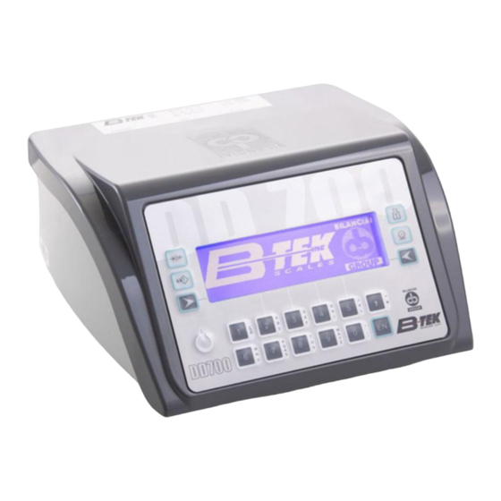
DD700 Technician's Service
Manual
BTEK
September
2023
This guide is intended to supplement and simplify other product technical manuals. The focus is to instruct on setting
up / troubleshooting the scale and communication ports on a DD700 indicator. See Use, Maintenance, and
Installation manual, Installation Manual, or Advanced User Manual for overall product information.
Distribution without consent of B-TEK scales, LLC is prohibited, for use by Heavy Capacity dealers only.
Page | 1
Advertisement
Table of Contents

Subscribe to Our Youtube Channel
Related Manuals for B-TEK Scales DD700


Summary of Contents for B-TEK Scales DD700
- Page 1 This guide is intended to supplement and simplify other product technical manuals. The focus is to instruct on setting up / troubleshooting the scale and communication ports on a DD700 indicator. See Use, Maintenance, and Installation manual, Installation Manual, or Advanced User Manual for overall product information.
-
Page 2: Table Of Contents
Table of Contents MAIN SCREEN ..................................... 5 Scale Metrological Seal ..................................6 Sealing ......................................6 Access all parameters ..................................6 Access non metrological parameters ............................. 6 Legal for Trade Scale Information ..............................7 Printer and Remote Display Wiring ..............................8 Digital Scale Wiring .................................... - Page 3 How the user level diagnostics function ..........................23 User level diagnostics function, explanation of error symbols ....................24 Test Menu for Scale Diagnostics (In #1 Scales, not #3 terminal test) ..................25 Digital Scale Input Troubleshooting ..............................26 Replacing One or Two Digital Load Cells ............................28 Replacing Indicator –...
- Page 4 Firmware Update Continued ..............................61 Spare Parts and Optional Items ............................... 62 Page | 4...
-
Page 5: Main Screen
MAIN SCREEN 1. Zero 2. Auto Tare 3. Keyed Tare / Toggle Tare 4. Print 5. Power Button 6. Enter Button 7. ID# Soft Key – Start double weighing transaction 8. PID Soft Key – Start Stored Tare Transaction (Truck weight must be > Tare) 9. -
Page 6: Scale Metrological Seal
Scale Metrological Seal Sealing For models DD700 and DD700ic access to the set-up/calibration switch can be secured with a wire seal threaded through two drilled head screws on the back on the indicator. For model DD700i access to the setup/calibration switch can be secured with a wire seal threaded through two drilled head screws located on the faceplate of the indicator. -
Page 7: Legal For Trade Scale Information
Legal for Trade Scale Information Don’t forget to complete the scale capacity, e: resolution, CLC, and Sec C: information on the indicator. Recommend using a fine point sharpy marker. County / State sealers will red tag the scale for incomplete information. Page | 7... -
Page 8: Printer And Remote Display Wiring
Printer and Remote Display Wiring Cable Item# 835-300014 Note: Input and Output connections are not needed for remote without traffic light. Page | 8... -
Page 9: Digital Scale Wiring
Digital Scale Wiring Digital Junction Board Page | 9... -
Page 10: Analog Scale Connection
Analog Scale Connection 9-pin male connector. DESCRIPTION SIG- SIG+ EXC+ EXC- +SENSE -SENSE Serial Connections COM2 serial link 9-pin female connector. PIN DESCRIPTION RX422- RX232 TX232 Page | 10... -
Page 11: Com1
RX422+ TX422- TERMINATOR TX422+ COM1 PIN DESCRIPTION RX 232 TX 232 RTS 232 CTS 232 NC = Stand-by. Do not connect. Page | 11... -
Page 12: Rs232 / Rs422 / Rs485 Installation Guidance
RS232 / RS422 / RS485 Installation guidance CAUTION Maximum use conditions envisaged by standard RS232: Maximum transmission distance: 15 m / 50ft Maximum voltage at ends: ± 12 Vdc It is advisable to use a screened cable for connections to external devices. Remember to connect the screen to the metal part of the shell of the 9-pin connector on one end. -
Page 13: Inputs / Outputs
INPUTS / OUTPUTS Input connection CAUTION Electrical specifications Inputs: maximum voltage < 5 Vdc maximum current < 5 mA The inputs can be controlled by clean contacts or by NPN transistors (negative common connection). Output connection CAUTION Electrical specifications Outputs: switchable voltage <... -
Page 14: Accessing Scale Configuration
Accessing Scale Configuration Press Calibration 1. Press Calibration Button (SW2 between com and usb) / AKA Metrological Seal (See Page 6) 2. Press 5 to select English (Arrow next to #2 selects English) 3. Program code is displayed for 10 seconds 4. -
Page 15: Configuring Scale
Configuring Scale 1. Select #1 Metrological 2. Select #2 Capacity (Note: Legal for trade can be turned on after calibration) 3. Enter the full scale capacity, then press Enter “EN” 4. Select #4 Division 5. Scroll using 3 and 4 keys to select resolution, press 5, then ESC soft key 6. -
Page 16: Scale General Operation Configuration
Scale General Operation Configuration 1. From Scale Configuration, Select #2 General 2. #1 Digital Filter sets the number of readings taken per displayed value. 16 is a good starting point for a larger capacity scale, and 8 for smaller capacities. The higher the value, the slower and more stable the reading will be. -
Page 17: Digital Scale Parameters
Digital Scale Parameters 1. From Scale A, Select #3 Digital Scale Parameters, press 5 key 2. Select #1 N. of load cells, press 5 key 3. Use numeric keypad to enter number of digital load cells, Press Enter (EN) 4. Confirm changes by pressing the Yes soft key 5. -
Page 18: Digital Scale - Angular Calibration - Address Load Cells
Digital Scale – Angular Calibration – Address Load Cells Note: When recalibrating angular coefficients, manually reset all coefficients to “1”. See page 19 elect #5 Calibration, then press 5 key 2. Select #3 Angle Calibr., then press 5 key 3. Select #2 Calibration by side (1,3,..,4,2), then press 5 key for truck scales 4. -
Page 19: Manually Adjusting Angular Coefficients
Manually Adjusting Angular Coefficients 1. Press the EDIT soft key 2. Enter cell to modified using the keypad 3. Enter the updated Coefficient using the keypad (Comma Key is the Decimal Point) 4. Press the Enter (EN) key 5. Modified coefficient is stored in the indicator. Continue updating other load cells, when finished press the #5 “” to transfer updated coefficients to the load cells. -
Page 20: Calibrating Zero-Span For Analog And Digital Scale
Calibrating Zero-Span for Analog and Digital Scale 1. Select #5 Calibration, then press 5 key 2. Select #1 Execute, then press 5 key 3. Select #1 Standard Calibration, then press 5 key 4. Select #1 Zero Full Scale, then press 5 key 5. -
Page 21: Error Codes
Error Codes Scale Errors Problem Cause Remedy Reduce the weight to a value lower than the OVERLOAD The scale is overloaded maximum capacity so that it is suitable to the weighing area The scale is negative by at Press the reset key: least 20 divisions. -
Page 22: Scale Error Fault Codes And Remedies
Scale Error Fault Codes and Remedies Problem Cause Remedy - 01 - Incorrect or missing load Check extension cable, junction box and load Faulty converter cell connection cells - 01 - (*) Return signal from load Check the load cell is accurate and works within Faulty converter cell out of range tolerances. -
Page 23: Diagnostics
Diagnostics The diagnostics screen is accessed from the user menu, 15 diagnostics. Option #2: scales test menu. For initial troubleshooting use the user menu (Not the “test” in scale parameters), all errors will reset on power reboot. 1. Indicators scale card address 2. -
Page 24: User Level Diagnostics Function, Explanation Of Error Symbols
Asterisk(*) added, the cell or cells in the error status are now 0410 490046 1.10 marked with an asterisk, which remains even if the cause of the DD700 59300004 error is eliminated. V1.14 The asterisk appears when one or more cells fail to communicate with the terminal for three consecutive times and the terminal gives error - 01 -. -
Page 25: Test Menu For Scale Diagnostics (In #1 Scales, Not #3 Terminal Test)
Test Menu for Scale Diagnostics (In #1 Scales, not #3 terminal test) 1. Within the Scales Parameters, select #6 Test, then press the 5 key 2. Displayed are the test parameters 3. Internal counts from each cell can be displayed and update continuously. “----” is displayed when communication is lost. -
Page 26: Digital Scale Input Troubleshooting
Digital Scale Input Troubleshooting Use these instructions to troubleshoot digital scale indicators displaying an – 01 – Error code and diagnostics are showing no load cell communication. If your indicator tests good, continue troubleshooting the scale’s load cells, cables, and junction box. Items Needed: Voltmeter Set to VDC, DB15 Male Connector (or Homerun Cable), Phillips screwdriver to open housing. - Page 27 5. Depending on observation in step 4 do the following. a. If lights never blink, make sure card is fully seated on pins, then consider replacing card. b. If the lights blink dim, replace the card. c. Carefully check temperature of card (Can burn you), replace if over 140 F. d.
-
Page 28: Replacing One Or Two Digital Load Cells
If replacing two load cells, keep note of the serial number for each position. Turn DD700 power on. Power button is located on front lower left corner of the keypad. After the B-TEK screen, display should show error code -07-. This means that a new load cell(s) has been found and it has no calibration information stored in it. -
Page 29: Replacing Indicator - Uploading From Cells
Replacing Indicator – Uploading from Cells Connect homerun cable, power cord, and printer cable to new indicator. Switch power on. Power switch is located on rear of indicator. After splash screen, display should show error code -08-. This means that the indicator is new and has no calibration information. -
Page 30: Test Digital Cells - Cell Emergency Routine
Test Digital Cells – Cell Emergency Routine 1. Select #5 Maintenance, then press 5 key 2. Select #8 Cell Emergency Routine, then press 5 key 3. In the digital gathering box, connect load cell into cell position #1, and terminator into cell position #2 (Terminator in pins 1 & 2). Optional, if defaulting all load cells in scale, leave all load cells connected. -
Page 31: Configuring Operating Mode
Configuring Operating Mode 1. From setup menu, select #2 personalization, then press 5 key 2. Select #1 operating modes, then press 5 key 3. Select #4 Operation, then press 5 key 4. Select #1 single weighing select, or #2 double weighing depending on operation 5. -
Page 32: Configuring Database Files
Configuring Database Files 1. From setup menu, select #2 personalization, #4 Files, #2 File Status 2. Select the file to be modified 3. To delete a file, select #1 Delete 4. Press the right arrow to confirm deletion of file. This will remove Product or Client from the print ticket. -
Page 33: Rcd / Rcd Id File Reset Procedure
RCD / RCD ID File Reset Procedure 1. Press Menu arrow key (on left side of display). Press the number 5 key to select “Data Management” 2. Press the number 5 key to select “Code Management” 3. Press the number 4 key to scroll down to “ID List”. Press the number 5 key to select “ID List” 4. -
Page 34: Configuring Printer
Configuring Printer 1. Select Personalizations, Operating Modes, #5 Printer, press the 5 key to select. 2. Select #1 Model, press the 5 Key to select 3. Select the printer model 4. Printer options are displayed, line feed sets inbound ticket start position, and Output Line Feed sets the outbound ticket start position. -
Page 35: Serial Output Config. (Remote / Computer)
Serial Output Config. (Remote / Computer) 1. Select #2 Personalizations, then press the 5 key to select. 2. Select #2 Outputs, then press the 5 key to select. 3. Select Serial / Opt., then press the 5 key to select. 4. -
Page 36: Print Net Tons On Standard Ticket
Print Net Tons on Standard Ticket Press MENU softkey (to the left side of display). User menu is displayed. Press Select (#5 key) to choose “Data Management”. Use down arrow softkey (#4 on keypad) to highlight “Coefficient Management”. Press Select (#5 key) Verify #2 Operation is set to “Multiplication”... - Page 37 To Change the wording on the Print Can be done by modifying Message number 95 Coefficient and message 97 Results in the Setup menu. Follow path: Personalizations/spec. Customizations/Messages/Modify Key in 97, then Enter Press Delete soft key Enter “Net Ton” using alpha numeric keys or usb keyboard Press ESC softkey 6 times to save and return to the normal weighing screen Page | 37...
-
Page 38: Modifying Messages / Print Text
Modifying Messages / Print Text Follow path: Personalizations/spec. Customizations/Messages/Modify Below are commonly changed messages, for a complete list print the messages. Changing these will modify what prints on the ticket. If you want to print weight data only and do not want to spell out Gross, Tare, Net delete text in 4, 5, and 6. -
Page 39: Advanced Ticket Formatting - Dialogic
4. Press “Select” and the indicator will go into a special interfacing mode. 5. Plug your cable into the corresponding DD700 com port you chose in step 3 and to the computer’s serial port. *You may be plugging it into a USB-to-Serial converter. * SOFTWARE STEPS: 1. - Page 40 6. Next, go to the toolbar at the top and choose “Terminal -> Import” and the following window will pop up. Ensure the Port number is the one you’re plugged into. Check all except Data Files. 7. In the “Select Items to download from the terminal” section, I would recommend checking everything listed.
- Page 41 8. After you receive an “Import Done” message, you will need to expand the “Print Layouts”, then the “Tickets” section on the left of the screen, as shown below. 9. Highlight the ticket you want to edit, and click on the “Configure” button. In the example here, I have chosen the “Single-Weighing”...
- Page 42 10. Once the ticket customization tool is up, you can then design a ticket accordingly! Below is an example of one but note how there are TWO of each field; one for the “Description” and one for the “Value” (just click that drop-down in “Type” for that option). VALUE MUST BE SELECTED TO SHOW THE VALUE, OR YOU’LL JUST HAVE FIELD DESCRIPTION LIKE YOU SEE IN MY EXAMPLE!! Essentially, what you see is what you get.
- Page 43 “Data Files” box checked in Step #6. 13. And finally, setup your DD700, D410, D450, or D800 to utilize “Personalized” prints when you go to setup Personalizations -> Operating Modes-> Printer -> Prints. )
-
Page 44: Configuring Inputs And Outputs - Setpoints
Configuring Inputs and Outputs - Setpoints This example demonstrates configuration of a traffic Light Signal on Page 8 1. Select #2 Personalizations, #2 Outputs, #2 Input/Output 2. Select #2 Output 3. Select #1 Output01 4. Select #2 Operation 5. Scroll using 3 and 4 keys to select operation type Green 6. -
Page 45: Configuring Remote Zero Input
Configuring Remote Zero Input Connect a momentary-contact pushbutton or switch across terminals 1(input 1) and 3(common) of JI/O terminal block on rear of indicator. Polarity does not matter Switch off indicator. Hold left arrow key(third button down on left side of the display) in on front of indicator and switch on the indicator while holding the arrow key in. -
Page 46: Setting Time And Date
Setting Time and Date 1. In the User Menu, scroll down to #9 Date Time, then Select 5 key 2. Select #2 Change, then use 2, 3, 5, and 5 to adjust data and time. 3. Select right arrow button to end and save Page | 46... -
Page 47: Inbound / Outbound Weighing
Inbound / Outbound Weighing Inbound: Truck pulls on scale (light or heavy) Press “I.D.#” key ( on keypad). Key in truck’s ID# (keys are alphanumeric like cell phone, so you may have to press a key repeatedly to get desired character) Press key (enter) Display returns to weight on scale with “RcD ID: 1234”... -
Page 48: Weighing With Stored Truck Tares
Weighing with Stored Truck Tares *Initially, you will have to weigh each truck and record it’s tare weight. Once it is stored in memory, it can be recalled over and over again.* Press “P.I.D. key (number 3 on the keypad) Key in ID# for truck’s stored weight (keys are alphanumeric like cell phone, so you may have to press a key repeatedly to get desired character) Press “EN”... -
Page 49: Changing Scale Type / Set Up Repeater
Changing Scale Type / Set Up Repeater 1. Select #1 Scales with the 5 key 2. Select 1 1 with the 5 Key 3. Select #1 Scale Analog or Digital with the 5 key 4. Select the right arrow key (Yes) 5. -
Page 50: Set Up Repeater Continued
Set Up Repeater Continued 1. Select the com port to be used, RS232, RS422, or Ethernet can be used 2. Configure the com port settings to match the master indicator. 3. Under #2 String settings, select string to be used. Extended string or CMA string work for repeater applications. -
Page 51: Axle Weighing And Totalizing Setup
Axle Weighing and Totalizing Setup 1. Press calibration button, navigate to personalizations/operating modes/Operation/Single Weighing. Then select #1 Standard 2. Escape twice, then select weighing 3. Select #3 Automatic Printing, then select Yes if you want the weight printed automatically, or leave set to No if you want manual operation. 4. -
Page 52: Tcp/Ip Ethernet Output Configuration
Then select download on the page shown below. 1. Install the option card into one of the available option card slots on the DD700 2. Connect the cross over Ethernet cable and power on the indicator. You will be prompted to... - Page 53 The last number should be unique from the others. 4. Open Digi Device discovery. The digi program should find Ethernet card in DD700 with default IPaddress, Subnetmask, gateway, port. Note: If the Digi Device web interface will not open in Internet Explorer check the settings in the following: open Internet Explorer click on tools, Internet options, connections, LAN settings, uncheck box in proxy server section if box is checked.
-
Page 54: 4-20 Ma Option Card Setup And Calibration
4-20 mA Option Card Setup and Calibration **The analog output option board for a DD700 has a 3-pin connector on it. Pin #1 is the -4 to 20mA output and Pin #2 is the +4 to 20mA output. Pin #3 is used with Pin#2 for a 0 to 10VDC output.**... -
Page 55: Bypassing The On-Off Switch (Always On)
Bypassing the On-Off Switch (Always on) Open the indicator enclosure, then locate the jumper labeled J4 next to the lithium battery. Install a jumper while indicator is powered down. Note: Jumper is not supplied with indicator and will need to be purchased. Plug in the indicator, it should turn on immediately. -
Page 56: Memory Recovery Procedure
Memory Recovery Procedure (Turning off Storing CSV) 1. Press “MENU” softkey. It is to the left of the display, left blue arrow The User Menu will now appear. 2. select number 7 Memory status: Free memory xx%” is highlighted. Message will be displayed “ Memory recovery Procedure? You will have a choice of NO being this key: Or YES being this key 3. -
Page 57: Firmware Update
3. Next, we need to ensure that you have a USB drive. This one that comes with a new DD700 should work fine. There are other ways to update via serial line, this guide focuses on using the USB flash drive. -
Page 58: Firmware Update Continued
Firmware Update Continued In that folder, create another folder titled “FIRMWARE”: 6. And in that folder, place the actual firmware file: 7. It is very important to get the naming of the folder, all caps and all, and drive path correct, or else the indicator will not find the file. -
Page 59: Firmware Update Continued
Firmware Update Continued 8. Power up your indicator and plug up your B-TEK drive in the back of the DD700 in the USB port… at some point, you will hear an audible beep once the USB drive is recognized: 9. Press the calibration switch and go to English; at this step you can also... -
Page 60: Firmware Update Continued
Firmware Update Continued 11. Once you press the “YES”, you will now be at the post-firmware-delete screen. Notice that the contrast has changed as well: 12. The Left and Right blue/white buttons will NOT line up perfectly with these two options, but they are the ones you press. - Page 61 Firmware Update Continued 15. There will be the deletion status… 16. And then a programming status… 17. And finally, turn off terminal when finished. Note: The settings of forced zero = 3e and auto zero = 3e will work best with this firmware on a truck or rail scale.
- Page 62 DD700 4-INPUT / 4-OUTPUT OPTION CARD 899-100138 OC1845 DD700 SINGLE SERIAL RS-232 / 422 / 485 OPTION CARD 899-100139 OC1846 DD700 PROFIBUS DP OPTION CARD (MB has to be REV D) DD700 ETHERNET IP OPTION CARD 899-100140 OC1847 899-100141 OC1848...
Need help?
Do you have a question about the DD700 and is the answer not in the manual?
Questions and answers