Table of Contents
Advertisement
Advertisement
Table of Contents

Related Manuals for 3S MP 100

Summary of Contents for 3S MP 100
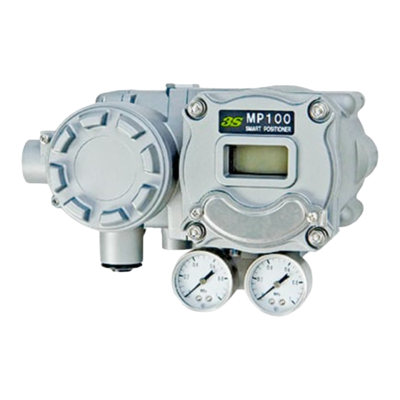
- Page 1 Smart Positioner Operating Manual MP 100 3S Co., Ltd. (E)IM-MP100-00-R10...
- Page 2 Safety precautions Cautions and Warnings – read before operating Warning! Indicates a situation where incorrect operation while failing to heed the warning could result in death or serious injury if not avoided. ■ To use Flame-proof equipment, be sure to refer to the ANNEX1 and follow the instructions. ■...
-
Page 3: Table Of Contents
- Index - 7-3-4-4 Valve closing function ....16 1. Introduction ..........1 7-3-4-5 Characteristics ......17 2. Specifications ..........1 7-3-4-6 Actuator ........18 3. Operation principle ........2 7-3-4-7 Single / Double action ....18 7-3-4-8 Direction of rotation ....18 4. -
Page 4: Introduction
1. Introduction MP100 smart positioner is 2 wire type E/P Positioner equipped with a microprocessor which control a valve by receiving 4-20mA of input signal. Auto-tuning function is equipped by default. Feedback signal or HART communication is available for comprehending valve status. 2. -
Page 5: Operation Principle
3. Operation principle MP100 controls the degree of opening of the control valve in response to the input signal of 4 to 20mA, which is originating from the signal source, such as an electronic controller. Internal sensor detects the degree of opening of the control valve. MP100 captures the input signal and sensor information to the microprocessor. -
Page 6: Installation
4. Installation 4-1 Prior confirmation 1) Position of Sensor Shaft Feedback lever is used within the range of the sensor shaft ▲ mark is within ± 50°. It is recommended that the angle difference between the opening 0% and the 100% will be more than 40°. - Page 7 2) Install positioner and lever ① Install positioner When the sensor angle is 0° (Valve Stem and Feedback lever is vertical), the positioner Feedback lever is mounted the positioner so that the horizontal. When this location is shifted, it is cause of linearity errors.
-
Page 8: Installing To Rotary-Actuator
4-3 Installing to Rotary-actuator (Namur clumping type) 1) Assemble Namur clamp A (Positioner side) Insert Namur clamp A into boss and fasten screw (Keep the marked range). As shown in the figure below, the position where the ▲ mark and the convex part is match is mounted so that the 50% opening. -
Page 9: Pneumatic Piping
5. Pneumatic Piping Use supply air that has been dried and filtered by 5 μ m or less filter to protect against moisture or oil or dust. ※(Single Acting) If input signal is increased, output pressure increase too. (Configuration is required to conform to the application signal increase to decrease output pressure) 【Single acting】... -
Page 10: Electric Wiring
6. Electric wiring 6-1 Wiring circuit 6-2 External connection Warning ・When wiring, Please turn off the power. ・Please installing in accordance with local recommended.When using Flame-proof equipment at hazardous areas, always wiring in accordance with 『ANNEX1 Instructions about Flame- proof type Equipment』. ・Be sure to close the unused connection port with a blind plug. -
Page 11: Feedback Signal Power And Load
6-3 Feedback signal power and Load resistance The load resistor connected determined based on the following equation. The load resistance is also considering conducting wire resistance. Load resistance (R + r)[ohm] ≤ (Feedback signal power[V] – 12[V]) / (20[mA] / 1000) The maximum power supply voltage is the 36V DC at Flame-proof and 24V DC at Non-explosion proof. -
Page 12: Adjustment And Setting
7. Adjustment and Setting Warning ・Do not open Main body cover and Terminal box cover with its power turned on. Always check that there is no explosive gas or vapor in that location to remove the cover (Main body cover or Terminal Box cover) of Fame-proof enclosure with the power * Button Cover is not Flame-proof enclosure. -
Page 13: Lcd-Display Description
7-1 LCD-Display description ④ ⑤ ② ③ ⑦ ① ⑥ Numerical display ① numeric portion of Display the setting parameters, input signal, or position value. ② Mode Display the mode of the value shown, SIG means ‘Displaying input signal value’ and POS means ‘Displaying position signal value’... -
Page 14: Menu Tree
7-2 Menu tree ※When the software revision is older than 0121, please contact because there is a different part. ※The soft revision can check it by MANU ⏎ SUB ⏎ INFO ⏎ SREV . 1.WARN 1.ERR Operation Mode 2.TUNE 2.ALM A*-* 3.DISP 4.MANU... - Page 15 1.DIAG 1.INPU 1.PROF 1.CO4mA 4? mA ※Previous Page 2.IOUT 2.FB 2.ALRM 2.CO20mA 20? mA 3.TORQ 3.TEMP 3.SHUT 4.D/R 4.TIME 1.MIN **.** mA 5.INFO 2.MAX **.** mA 1.VIEW **** k 2.CLR CLR? 1.TOTL **** k(D) 2.TERM 1.ALRM **** D 2.DATA **** H(D) 3.CLR CLR? 1.ALRM...
-
Page 16: Menu Description
7-3 Menu description Operation ・Use four buttons ▲, ▼, ⏎, ESC ・Press the ⏎ button to complete the operation ・Press the ESC button to cancel the operation ・Input signal should be kept to a minimum 4mA ・After finishing operation, press ESC button to get back to the operating mode (It would not be switched automatically) 7-3-1 Lock/Unlock Enable/Disable to change settings. -
Page 17: Auto-Tuning
7-3-3 Auto-tuning ALL : Start Auto-tuning for all setting A-1 : Start Zero-span and operation direction setting A-2 : Adjust torque motor setting A-3 : Adjust PID constant and input signal filter ○ Sequence ①Unlock LOCK ⏎ LK? ▼ ULK? ⏎ ②Tuning TUNE ⏎... - Page 18 7-3-4-2 FB Set open/close position manually linearity correction of valve position ○ Sequence ①Unlock LOCK ⏎ LK? ▼ ULK? ⏎ ②Operation MANU ⏎ SPLT ▼ FB ⏎ ZERO ⏎ ZST? ⏎ : Set current value as 0 % position ▼ SPAN ⏎ SST? ⏎ : Set current value as 100 % position ▼...
-
Page 19: Pid
7-3-4-3 PID Adjust PID Parameter, input signal filter and dead band ○ Sequence ①Unlock LOCK ⏎ LK? ▼ ULK? ⏎ ②Operation MANU ⏎ SPLT ▼ PID ⏎ P-GN ⏎ *** ⏎ : Set the total gain ▼ I-GN ⏎ **.** ⏎ : Set the integral gain ▼... -
Page 20: Characteristics
7-3-4-5 Characteristics Set characteristics ○ Sequence ①Unlock LOCK ⏎ LK? ▼ ULK? ⏎ ②Operation MANU ⏎ SPLT ▼ CHAR ⏎ SEL ⏎ LIN? ⏎ : Choose linear characteristics ▼ EQ? ⏎ : Choose near Eq% characteristics ▼ QO? ⏎ : Choose 'quick open' characteristics ▼... -
Page 21: Actuator
7-3-4-6 Actuator Choose Linear / Rotary mode. Choose mounting of the transmission pin in the case of Linear actuator. ○ Sequence ①Unlock LOCK ⏎ LK? ▼ ULK? ⏎ ②Operation MANU ⏎ SPLT ▼ L/R ⏎ LIN? ⏎ : Linear actuator mode, fixed transmission pin to the actuator side ▼... -
Page 22: Display Angle
7-3-4-9 Display angle Show the angle of sensor. When installing a positioner, used to check the value of the angle sensor. ○ Sequence ①Operation MANU ⏎ SPLT ▼ ANGL ⏎ ±**.*° ⏎ ○ Notice ・The maximum value that can be displayed is ±50°. -
Page 23: Sub
7-3-5 SUB Describe SUB menu below. (diagnostic function, position transmitter function, device information) 7-3-5-1 Diagnostic function Describe diagnostic function 7-3-5-1-1 Calibration & Diagnostic of input signal Adjust calibration and diagnose of input signal ○ Sequence ①Unlock LOCK ⏎ LK? ▼ ULK? ⏎ ②Operation MANU ⏎... -
Page 24: Diagnostic Of Sensor
7-3-5-1-2 Diagnostic of Sensor Diagnose Sensor and set partial stroke ○ Sequence ①Unlock LOCK ⏎ LK? ▼ ULK? ⏎ ②Operation MANU ⏎ SPLT ▼ SUB ⏎ DIAG ⏎ INPU ▼ FB [Alarm Set] ⏎ ALRM ⏎ MIN ⏎ ***.* % ⏎ : Set lower limit ▼... -
Page 25: Calibration & Diagnostic Of Thermometer
7-3-5-1-3 Calibration & Diagnostic of thermometer Show the internal temperature ○ Sequence ①Unlock LOCK ⏎ LK? ▼ ULK? ⏎ ②Operation MANU ⏎ SPLT ▼ SUB ⏎ DIAG ⏎ INPU ▼ TEMP [Set temperature unit] ⏎ UNIT ⏎ CEL? ℃ ⏎ : Show in ℃... -
Page 26: Calibration Of Feedback Signal
7-3-5-2 Calibration of Feedback signal Below is operating sequence IOUT (Feedback signal) ○ Sequence ①Unlock LOCK ⏎ LK? ▼ ULK? ⏎ ②Operation MANU ⏎ SPLT ▼ SUB ⏎ DIAG ▼ IOUT ⏎ VIEW ⏎ **.** mA : Display feedback signal value ▼... -
Page 27: Information
①Unlock LOCK ⏎ LK? ▼ ULK? ⏎ ②Operation MANU ⏎ SPLT ▼ SUB ⏎ DIAG ▼ INFO ⏎ MANU ⏎ 3S : Display manufacturer ▼ MODL ⏎ MP : Display model code ▼ HREV ⏎ **** : Display hardware revision of circuit board ▼... -
Page 28: Alarm Display
7-3-6 Alarm display ALM , ERR and each code displayed at the top of the LCD when malfunction occurs. Refer to the following table for further details 7-3-6-1 Alarm code It will be displayed when it exceeds the alarm set value. Code Meaning Details... -
Page 29: Error Code
7-3-6-2 Error Code Code Meaning Details CPU Error 1 CPU was hung-up and restarted CPU Error 2 CPU clock error EEPROM Error1 ROM data which normally replaced is broken. * This error indicates the data of accumulation, open/close position, PID parameter is broken. EEPROM Error2 Data loss (Not E3. -
Page 30: A/M Selector (Only For Single Action)
8. A/M Selector (Only for Single action) To use in manual mode turn the Selector to M (counter-clockwise).The actuator can be operated in manual mode adjusting the supply pressure reduction valve. ※ A/M Selector is left-hand thread. Do not remove or loosen TP screw. ※... -
Page 31: Maintenance
9. Maintenance Carry out regular inspections for maintenance based on Regular Inspection Manual table. They can be different for different circumstances. Making your own Regular Inspection Manual is recommended. ・For maintenance of Flame-proof type Equipment, see “ANNEX1”. -Regular Inspection Manual- Interval of Check point Inspection... -
Page 32: Troubleshooting
③ Remove the O-rings from pilot case. [See figures below] Replacement ① Place the new O-rings to the pilot case. In case of Single- action, make sure the shim is placed. If you lost the shim, use the new shim included in the repair kit. Caution! Different numbers of the O-rings and shim are used for Single- action and Double- action. - Page 33 Modify setting Linear and rotary settings are wrong Refer to 7-3-4-6 Actuator ※Perform Sensor Unit and Torque Motor Unit shall be replaced in our factory. Please contact us when it is necessary. <Feedback signal> No power supply Rewiring DC power Wrong with + / - wiring supply Not working...
-
Page 34: Outline Dimension
11. Outline Dimension S U P Air Connection Port Supply Port Output Port Gauge Port Mark 1 Rc1/4 Rc1/4 Rc1/8 1/2NPT 1/4NPT 1/8NPT Rc1/4 Rc1/4 1/8NPT Cable Entry Conduit Cable Entry Conduit Mark 2 G1/2 1/2NPT M20×1.5... -
Page 35: Model Notation
12. Model notation Basic Model Code Description MODEL UNIT Smart Series 100Series Standard Type Ex d IIC T6 (TIIS etc.) Ex d IIC T6 Gb (IECEx) Housing ※1 Ex db IIC T6 Gb (NEPSI) II 2 G Ex d IIC T6 Gb (ATEX) Rc(PT)1/4 Single acting Pneumatic piping Rc(PT)1/4 Double acting... -
Page 36: Annex1
ANNEX1 Instructions about Flame-proof type Equipment 1. Introduction When using Flame-proof equipment, thoroughly review the notes on this clause, please use it correctly. Do not open when an explosive atmosphere may be present. 2. Electrical Equipment of Flame-proof Construction The Flame-proof construction is of completely enclosed type and its enclosure shall endure explosive pressures in cases where explosive gases or vapors entering the enclosure cause explosion. - Page 37 【IECEx Flame-proof】 Ex d ⅡC T6 Gb Equipment Protection Level (indication by IEC) Ignition temperature of gas or vapor in the atmosphere is over 85℃ Atmosphere of Group ⅡC gases For flameproof enclosure The symbol Ex (indication by IEC) Flame-proof equipment may be installed, with targeted gases, in a hazardous area in Zone 1 or 2. Flame-proof equipment shall not be installed in a hazardous area in Zone 0.
- Page 38 AMBIENT TEMP. -20℃ ≤ Tamb ≤60℃ EXPLOSION PROOF Ex d ⅡC T6 SER. NO. 2-6-7, Ukima, Kita-ku, 3S Co., Ltd. Tokyo, 115-0051, Japan See Instruction manual 【IECEx, ATEX, KOSHA Flame-proof】 - Marking of Flame-proof - IECEx TIIS 16.0004X DEKRA 15ATEX0075X...
- Page 39 【NEPSI Flame-proof】 - Marking of Flame-proof -...
- Page 40 5. Wiring of Flame-proof Equipment 【TIIS Flame-proof】 In the case of TIIS (Japanese certificator) flameproof enclosure’s regulations, the cable gland and the blind plug has been approved in the state in combination with the equipment. Accordingly, only the cable gland / blind plug specified by us are permitted. Following table shows cable glands specified by us.
- Page 41 【IECEx, ATEX Flame-proof】 For Installation, follow the EN/IEC60079-14 For wiring connection port of positioner, use cable gland and blind plug corresponding to Ex d IIC approved. Please use the cable gland is selected with the correct size to fit the cable used. Apply a sealant to the threads of the connection port for waterproofing.
- Page 42 6. Maintenance of Flame-proof Equipment For maintenance of Flame-proof Equipment, please according to the following. Details of maintenance, please conducted in accordance with national legislation of the country to be used. (1) Maintenance Flame-proof equipment shall not be maintenance with its power turned on. Always check that there is no explosive gas or vapor in that location to remove the cover (Main body cover or Terminal Box cover) of Flame-proof enclosure with the power on.
- Page 43 3S Co., Ltd. https:/www.posi3s.com/ ■Head Quarter and factory:2-6-7, Ukima, Kita-ku, Tokyo, 115-0051, JAPAN Phone: +81-3-3558-6341 Fax: +81-3-3558-6371...
Need help?
Do you have a question about the MP 100 and is the answer not in the manual?
Questions and answers