
Related Manuals for ZNTS WF320348AAB


Summary of Contents for ZNTS WF320348AAB
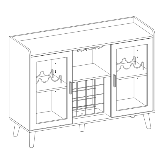
- Page 1 Bar Cabinet WF320348AAB Assembly Instructions - Please keep for future reference Important – Please read these instructions fully before starting assembly...
- Page 2 Safety and Care Advice Important – Please read these instructions fully before starting assembly • To reduce the likelihood • Do not stand or apply weight to • Check you have all the of damage to your product, the product during assembly. components and tools listed on make sure your power drill This may cause damage.
- Page 3 Using Camlocks Step 1 Step 2 DO NOT OVER TIGHTEN. Connect the male Push the male camlock camlock as diected in into the entry hole. the assembly instructions using a scewdriver . Step 4 Step 3 Insert the femle Turn the female camlock camlock as shown in the clockwise with a instruction .
- Page 4 Assembly Instructions...
- Page 5 Part List : WF320348AAB Please check you have all the panels listed below 1 PC 1 PC 1 PC 1 PC 1 PC 1 PC 1 PC 2 PCS 1 PC 2 PCS Hardware 1 PC 2 PCS 1 PC...
- Page 6 Hardware list : WF320348AAB Please check you have all the panels listed below Note: The quantities below are the correct amount to complete the assembly. In some cases more fittings may be supplied than are required. Male Camlock x 14...
- Page 7 Assembly Instructions Step 1 C x 12 Step 2 F x 2...
- Page 8 Assembly Instructions Step 3 F x 2 After After Before Before Arrow direction forward Step 4 A x 4 C x 4...
- Page 9 Assembly Instructions Step 5 E x 6 Before Step 6 B x 4...
- Page 10 Assembly Instructions Step 7 Step 8 A x 4...
- Page 11 Assembly Instructions Step 9 A x 6 C x 6 Step 10 B x 4...
- Page 12 Assembly Instructions Step 11 B x 3 Step 12 B x 3...
- Page 13 Assembly Instructions Step 13 Step 14 I x 4...
- Page 14 Assembly Instructions Step 15 M x 1 N x 1 Step 16 F x 8...
- Page 15 Assembly Instructions Step 17 I x 4 V x 4 W x 20 Step 18 J x 4 L x 4 T x 1 Need two people to move and flip...
- Page 16 Assembly Instructions Step 19 Q x 1 Step 20 P x 4...
- Page 17 Assembly Instructions Step 21 D x 8 Step 22 Arrow direction forward...
- Page 18 Assembly Instructions Step 23 R x 24 Step 24 E x 8 K x 4 O x 2...
- Page 19 Assembly Instructions Step 25 E x 8 Step 26 E x 8...
- Page 20 Assembly Instructions Step 27...
- Page 21 Assembly Instructions Step 28 G x 12 H x 12 U x 4 Step 29 Effective distance of light control: within 3 meters...
- Page 22 Assembly Instructions Step 30 The unit is floor standing, but it is S x 2 recommended that the unit is secured to the wall. 1. Move the unit into desired position. 2. Mark the wall with a suitable scribe the position of the fixing holes.
Need help?
Do you have a question about the WF320348AAB and is the answer not in the manual?
Questions and answers