Metabo B 32/3 - Drill Manual
- Original instructions manual (72 pages) ,
- Brochure (34 pages) ,
- Original instructions manual (61 pages)
Advertisement
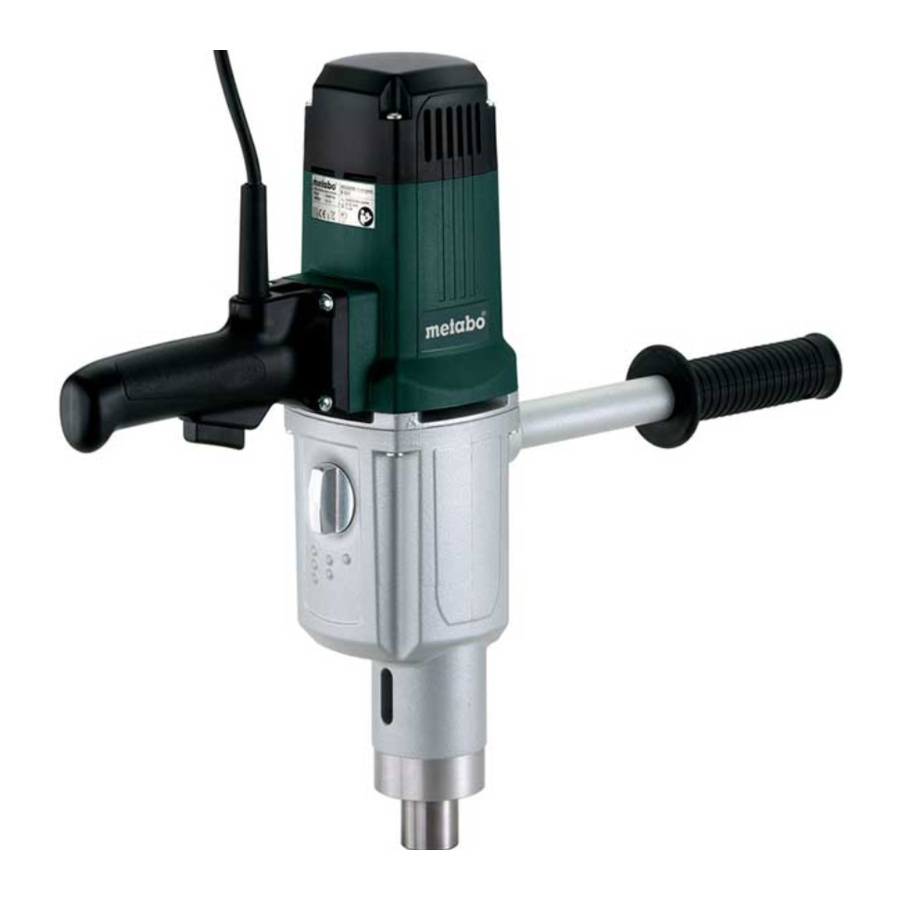
Specified Use
This machine is designed for drilling in metal, wood, plastics, and similar materials. The maximum permissible tool diameter when drilling with twist drill bits in steel is 32 mm.
Machines with material number 600323000 may only be used in drill stand 627100000 (see fig. B).
 When using the machine in the drill stand, observe the operating instructions of the drill stand!
The user bears sole responsibility for any damage caused by inappropriate use.
Generally accepted accident prevention regulations and the enclosed safety information must be observed.
General Safety Information
For your own protection and for the protection of your power tool, pay attention to all parts of the text that are marked with this symbol!

Read the operating instructions to reduce the risk of injury.

Read all safety warnings, instructions, illustrations and specifications provided with this power tool. Failure to follow all instructions listed below may result in electric shock, fire and/or serious injury.
Save all warnings and instructions for future reference.
Always include these documents when passing on your power tool
Special Safety Instructions
Safety instructions for all operations
- When working with the power tool wear hearing protection. Exposure to noise can cause hearing loss.
- Use the additional handle. Loss of control can cause personal injury.
- Brace the power tool properly before use. This power tool produces a high output torque. If the power tool is not braced properly during operation, loss of control may occur, resulting in personal injury.
- Hold the power tool by the insulated gripping surfaces when performing an operation where the cutting accessory may contact hidden wiring or its own cord. Cutting accessory contacting a "live" wire may make exposed metal parts of the power tool "live" and could give the operator an electric shock.
- If the accessory jams, stop operating the feed and switch off the tool. Check the reason for jamming and eliminate the cause for jammed tool inserts.
- If you want to start the drill with the accessory stuck in the workpiece, check that the accessory rotates freely before switching on. If the accessory jams, it may not rotate and this may overload the tool or cause the drill stand to detach from the workpiece.
- When drilling through walls or ceilings, ensure that people and the work area on the other side are protected. The accessory can go beyond the hole and endanger persons there.
Safety instructions when using long drill bits:
- Never operate at higher speed than the maximum speed rating of the drill bit. At higher speeds, the bit is likely to bend if allowed to rotate freely without contacting the workpiece, resulting in personal injury.
- Always start drilling at low speed and with the bit tip in contact with the workpiece. At higher speeds, the bit is likely to bend if allowed to rotate freely without contacting the workpiece, resulting in personal injury.
- Apply pressure only in direct line with the bit and do not apply excessive pressure. Bits can bend causing breakage and loss of control, resulting in personal injury.
Additional safety instructions
Pull the plug out of the plug socket before any adjustments or servicing are performed.
Take care to avoid gas, electricity, and water supplies!
Avoid inadvertent starts by always unlocking the switch when the plug is removed from the mains socket or in case of a power cut. Keep your hands away from the rotating tool!
Remove chips and similar material only with the machine at a standstill.

must be exercised when driving screws into hard materials (driving screws with metric or imperial threads into steel)! The screw head may break or high reverse torques may build up.
High forces are released if the tool jams or catches. Always hold the machine firmly, adopt a steady stance and focus on your work.
Secure small workpieces, for example by clamping them in a vice.
Do not keep the ventilation slots closed.
When using the machine with material number 600323000 in the drill stand 627100000, all operating instructions of the drill stand must be observed!
Reducing dust exposure:
Some dust created by power sanding, sawing, grinding, drilling, and other construction activities contains chemicals known to cause cancer, birth defects or other reproductive harm. Some examples of these chemicals are:
- Lead from lead-based paints,
- crystalline silica from bricks and cement and other masonry products, and
- arsenic and chromium from chemically treated lumber.
Your risk from these exposures varies, depending on how often you do this type of work. To reduce your exposure to these chemicals, work in a wellventilated area, and work with approved safety equipment, such as those dust masks that are specially designed to filter out microscopic particles.
This also applies to dust from other materials, such as some timber types (like oak or beech dust), metals, asbestos. Other known diseases are e.g. allergic reactions, respiratory diseases. Do not let dust enter the body.
Observe the relevant guidelines and national regulations for your material, staff, application and place of application (e.g. occupational health and safety regulations, disposal).
Collect the particles generated at the source, avoid deposits in the surrounding area.
Use suitable accessories for special work. In this way, fewer particles enter the environment in an uncontrolled manner.
Use a suitable extraction unit.
Reduce dust exposure with the following measures:
- do not direct the escaping particles and the exhaust air stream towards yourself or nearby persons or towards dust deposits,
- use an extraction unit and/or an air purifier,
- ensure good ventilation of the workplace and keep it clean using a vacuum cleaner. Sweeping or blowing stirs up dust.
- Vacuum or wash protective clothing. Do not blow, beat or brush protective gear.
Overview

- Side handle* (only 600323260)
- Adapter* (only 600323260)
- Thread for screwing in the adapter (only 600323260)
- Handle
- Trigger
- Thumb-wheel for gear selection
- Slot on machine neck
- Removal tool
- Drill spindle
- Tool holder
- Locking button (only for use in drill stand 600323000)
* Depends on variant
Initial Operation
Before commissioning, check that the rated mains voltage and mains frequency stated on the type plate match your power supply.
Always install an RCD with a maximum trip current of 30 mA upstream.
Extension cables must correspond to the power consumption of the machine (Technical Specifications). If using a roll of cable, always roll up the cable completely.
Assembly of side handle (only for 600323260)
When the drill bit jams, very high torques may be present. Therefore, for safety reasons, always use the additional handle () with adapter (). In the event of jamming, it is not sufficient to hold the machine only at the handle (). There is a risk of injury to the user.
See fig. A: Screw additional handle () into the thread () of the adapter () and the adapter () into the thread on the device and tighten both firmly by hand.
Due to the high torque that can occur when operating the tool, the tool must be braced against a solid object.
Use
Switching on and off
Avoid load on the machine until it come to a standstill.
Torque activation:
Switching on: press the trigger switch ().
230 V: Press in the trigger switch to increase the rotational speed.
Switching off: release the trigger switch ().
Continuous operation (ONLY for use in drill stand):
Switching on: press the trigger switch () and lock with locking button ().
Switching off: press and release the trigger switch ().
Use the locking button () only when the machine is in the drill stand.
The locking button () must be released after every machine-related standstill or after a current interruption to prevent accidental restart of the machine (risk of injury)!
Three-speed gearing
Do not actuate the thumb-wheel () unless the motor has completely stopped.
Select the desired speed by turning the thumbwheel ().
If necessary, the switching procedure can be supported by turning the drill spindle slightly.
Overload protection
The machine is equipped with a mechanical overload protection device to protect the operator, motor and tool.
If the tool jams suddenly, the drill spindle is decoupled from the motor by means of a slip clutch. The slip clutch is designed to absorb impact and excessive load. As it is only an aid, and does not provide total protection, you should always drill carefully. To retain its operability, it should slip through for a maximum of 2 seconds. In case of excessive wear, it must be replaced by an authorised specialist workshop.
Inserting and removing tool Inserting and removing tool
Perfect seating of the tool in the drill spindle () can only be guaranteed if the female taper of the drill spindle and the taper shank of the tool are free of dirt and grease.
Never use excessive force to press tools into the female taper of the drill spindle!
Always use sharp tools in perfect condition.
Switch off the machine. Pull the mains plug out of the socket.
Tools with taper shank MK3 can be inserted directly in the toolholder ().
Removing tool:
Insert the removal tool - with the sloping edge against the drill - in the slot () on the machine neck. If it cannot be inserted through the drill spindle, you should turn it slightly by hand. Drive out the tool by knocking lightly on the removal tool with a hammer.
Cleaning
Regularly clean the power tool's air vents.
Troubleshooting
Switching on the machine briefly reduces the voltage. Unfavourable mains power conditions may have a detrimental effect on other machines. Power impedances less than 0.35 ohm should not cause malfunctions.
Accessories
Use only genuine Metabo accessories.
Use only accessories that fulfil the requirements and specifications listed in these operating instructions.
Fit accessories securely. If the machine is operated in a holder: secure the machine well. Loss of control can cause personal injury.

- Metal drill bit with Morse taper shank
- Morse tapers for chuck with female taper
- Key-type chuck with female taper
- Metal drill bit
- Wood auger drill bit
- Forstner drill bit
- Reduction sleeves for tools with Morse taper
- Removal tool I Breast plate
For a complete range of accessories, see www.metabo.com or the catalogue.
Repairs
Repairs to electrical tools must ONLY be carried out by qualified electricians!
A defective mains cable must be replaced only with a special, original mains cable from Metabo available from the Metabo service. The connection cable must only be replaced by Metabo or an authorised customer service workshop.
Contact your local Metabo representative if you have Metabo power tools requiring repairs. For addresses see www.metabo.com.
You can download a list of spare parts from www.metabo.com.
Technical Specifications
Explanatory notes on the specifications. Subject to change in accordance with technical progress.
| B 32/3 | B 32/3 | |||
| 230 V *1) Serial Number: 600323000 | 230 V *1) Serial Number: 600323260 | |||
| T | Nm (in-lbs) | 1 | 190 (1682) | 190 (1682) |
| 2 | 120 (1062) | 120 (1062) | ||
| 3 | 90 (797) | 90 (797) | ||
| d 1max | mm (in) |  | 32 (1 1 / 4 ) | 32 (1 1 / 4 ) |
| d 2max | mm (in) |  | 70 (2 3 / 4 ) | 70 (2 3 / 4 ) |
| n 0 | min -1 (rpm) | 0-170 / 0-320 / 0-470 | 170 / 320 / 470 | |
| n 1 | min -1 (rpm) | 110 / 190 / 280 | 110 / 190 / 280 | |
| P 1 | W | 1750 | 1750 | |
| P 2 | W | 1200 | 1000 | |
| D | mm (in) | 65 (2 9 / 16 ) | 65 (2 9 / 16 ) | |
| MK | - | MK 3 | MK 3 | |
| m | kg (lbs) | 7,5 (16.5) | 7,5 (16.5) | |
| a h, D /K h, D | m/s 2 | 6,2 / 1,5 | 6,2 / 1,5 | |
| L pA /K pA | dB(A) | 96,5 / 5 | 94,5 / 5 | |
| L WA /K WA | dB(A) | 104,5 / 5 | 102,5 / 5 | |
T = Torque
d 1max=Max. drilling diameter in steel
d 2max=Max. drilling diameter in softwood
n0 =Idle speed
n1 =Speed at rated load
P1 =Rated input power
P2 =Power output
D =Collar diameter
G =Female taper of drill spindle
m =Weight without mains cable
Measured values determined in conformity with EN 62841.
![]() Machine in protection class II
Machine in protection class II
~ AC Power
The technical specifications quoted are subject to tolerances (in compliance with relevant valid standards).
Emission values
These values make it possible to assess the emissions from the power tool and to compare different power tools. The actual load may be higher or lower depending on operating conditions, the condition of the power tool or the accessories used. Please allow for breaks and periods when the load is lower for assessment purposes. Arrange protective measures for the user, such as organisational measures based on the adjusted estimates.
Vibration total value (vector sum of three directions) determined in accordance with EN 62841:
ah, D =Vibration emission value handle (Drilling in metal)
Typical A-effective perceived sound levels:
LpA = sound pressure level
LWA = acoustic power level
KpA, KWA = Uncertainty
Wear ear protectors!
Documents / Resources
References
Download manual
Here you can download full pdf version of manual, it may contain additional safety instructions, warranty information, FCC rules, etc.
Advertisement


Need help?
Do you have a question about the B 32/3 and is the answer not in the manual?
Questions and answers