Table of Contents
Advertisement
Quick Links
Advertisement
Table of Contents

Related Manuals for MasterPower Portable Energy Bank 3KW

Summary of Contents for MasterPower Portable Energy Bank 3KW
- Page 1 User Manual Portable Energy Bank 3KW/2.5KWh Version: 1.2...
-
Page 2: Table Of Contents
Table Of Contents ABOUT THIS MANUAL ............................1 Purpose ................................1 Scope ................................1 SAFETY INSTRUCTIONS ........................... 1 INTRODUCTION ..............................2 Basic System Architecture ..........................2 PRODUCT OVERVIEW ............................3 Main Unit ................................3 External Battery Module (Purchased separately) .................... 5 INSTALLATION .............................. -
Page 3: About This Manual
ABOUT THIS MANUAL Purpose This manual describes the assembly, installation, operation and troubleshooting of this unit. Please read this manual carefully before installations and operations. Keep this manual for future reference. Scope This manual provides safety and installation guidelines as well as information on tools and wiring. SAFETY INSTRUCTIONS WARNING: This chapter contains important safety and operating instructions. -
Page 4: Introduction
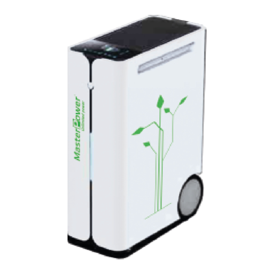
INTRODUCTION This is a portable energy bank for home and adventure. The power stations have a battery, inverter and smart charging technology all built into a neat plug and play unit. Plug and Play off-grid system provides multiple charging options, giving you the flexibility to charge from AC (wall outlet or generator) and solar panel. All units are provided multiple power sockets and USB charger ports, allowing to power your diverse electronic devices. -
Page 5: Product Overview
PRODUCT OVERVIEW Main Unit... - Page 6 Optional receptacles...
-
Page 7: External Battery Module (Purchased Separately)
External Battery Module (Purchased separately) -
Page 8: Installation
INSTALLATION Package Contents Before installation, please inspect the content. Be sure that nothing inside the package is damaged. You should have received the following items inside the package: Manual AC power cord Inverter with built-in battery Cable Gland x 2 Caster stopper x 2 Optional kit: PV connector... -
Page 9: Internal Battery Connection
Internal Battery Connection For safety concern, the internal battery is disconnected from the internal DC breaker before shipment. Before installation, please remove two screws from the top panel and turn on the internal DC breaker. Then, fix those screws firmly. ... -
Page 10: Pv Connection
PV Connection There are two methods to connect PV panels. 1. Connect directly on the terminal block. 2. Using a pluggable connector. Direct Terminal Connection 1. Take off the PV connector cover by removing screws as shown below. 2. Install the cable gland to connector cover. 3. -
Page 11: Ac Output Connection
AC Output Connection CAUTION: If signal unit operation, please close the cover of parallel socket to reduce risk of electric shock. Plug AC power cord on the AC output socket. Output powered when the main switch on the front panel pressed for 3 sec. In case the load rating higher than the socket could support (>13Amp), please connect the power cable on the AC output terminal block. -
Page 12: Usb Charger
USB Charger Use USB output cable (not provided) to charge your electronic devices. USB charger port could be turned on/off through the LCD operation. -
Page 13: Parallel Function
Parallel Function 1. Introduction This portable energy bank can be operated in parallel with 2 units. The supported maximum capacity is 6KW. If longer backup time is required, this unit can be connected with more battery modules up to 2 units. CAUTION: Parallel feature will be disabled when only PV power is available. - Page 14 3. Preparation Before connecting all wires, be sure to take off top panel and wire cover by removing six screws. Refer to below chart for the details. 4. External Battery Connection If longer backup time is required, it’s necessary to connect external battery modules. Maximum connection number is two.
- Page 15 6KW, 12.5KWh 6KW, 15KWh NOTICE: It’s not applied for common battery when expanding the output power with 2 units. External battery module only connects to its integrated main unit. Step 2: Connect extension port on the battery modules with RJ11 cables (supplied in the external battery module).
- Page 16 Expand Output Power and Battery Capacity 6KW, 7.5KWh 6KW, 10KWh 6KW, 15KWh 5. AC Output Connection Open the parallel port cover and use one parallel cable (purchased separately) to connect the parallel ports on the two main unit. Once paralleled units are powered on, you can plug devices on either Master or Slave unit. ...
-
Page 17: Operation
OPERATION The unit is equipped with rechargeable Lithium battery. Be sure to charge the battery at least more than 12 hours before initial use. To accurate the calculation of battery capacity, it’s recommended to have fully charged and discharged for 1~2 times. For long-term storage, it’s necessary to fully charge the battery, disconnect the internal DC breaker and store it in a cool, dry place. -
Page 18: Pages Information
Pages Information When the unit is turned on, the LCD display will show home page after few seconds. Home page: (tap icon 0.5s) indicates the summarized power flow and energy information. Battery page: indicates the battery cell and pack information. Cell indication in battery page: AC input page: indicates the AC input... -
Page 19: Configurations
Configurations Press icon for 3s to enter the setting menu. There are three sub-menus: Information, Basic and Advanced. Click icon again to exit setting return Home page. Information Basic Change the main page home page Turn on/off Wi-Fi module Turn on/off buzzer Setup date Setup Setup time... -
Page 20: Wi-Fi Connection
Configure the maximum charging current and limitation while charging from Utility Default: 50A, 30A Configure the limitation of discharging current Default: Disabled (means no limited) **Parallel application will disable the discharging limitation Configure the compatibility of AC input source Default: Utility Configure fault or overload behaviors Default: Disabled, Disabled Specific critical operations... -
Page 21: Prioritizing Energies Scenarios
Prioritizing Energies Scenarios (Noted: following demonstrations do not include and calculate the real conversion efficiency of the unit.) A) Load supplied from Solar firstly then Battery and Utility... - Page 22 B) Load supplied from Solar firstly then Utility and Battery...
- Page 23 C) Load supplied from Utility firstly then Solar and Battery...
-
Page 24: Clearance And Maintenance For Anti-Dust Kit
CLEARANCE AND MAINTENANCE FOR ANTI-DUST KIT Overview Every unit is already installed with anti-dusk kit from factory. This kit keeps dusk from your unit and increases product reliability in harsh environment. Clearance and Maintenance Step 1: Please loosen the screw on the rear-panel bottom side of the unit. Step 2: Then, dustproof case can be pulled out and take out air filter foam as shown in below chart. -
Page 25: Specifications
SPECIFICATIONS Rated Inverter Power 3000VA / 3000W INPUT Voltage 100VAC/110VAC/120VAC or 220VAC/230 VAC/240VAC Selectable Voltage Range 85VAC ~ 140VAC or 90VAC ~ 280VAC Frequency Range 50 Hz/60 Hz (Auto sensing) Max. Current and Protection 20A, Circuit breaker build-in OUTPUT AC Voltage Regulation (Batt. Mode) 100VAC/110VAC/120VAC or 220VAC/230VAC/240VAC ±... -
Page 26: Trouble Shooting
TROUBLE SHOOTING Warning and Fault List Code Type Code # Event Code Type Code # Event Fault Fan fault Fault Bus start fault Fault High PV-volt Fault Inv start fault Fault High bat-volt Fault High dc offset Fault Low bat-volt Fault Over-load Fault... - Page 27 Phenomenon and/or Possible cause What to do F05 shows. Check and verify if there is any load with short circuit condition? Remove the load and restart the unit again. If problem exist still, please contact the service center to repair. F14 shows.
-
Page 28: Appendix I: The Wi-Fi Operation Guide
Appendix I: The Wi-Fi Operation Guide 1. Introduction Wi-Fi signal can enable wireless communication between device and monitoring platform. Users can remote monitoring and controlling device easily by using the i.Solar APP. The major functions of this i.Solar APP: Delivers device status during normal operation. ... - Page 29 Once the Wi-Fi connection is successful, click the i.Solar App installed on the phone to enter the login page. Then, click the “Network Config” button to enter the Wi-Fi configuration page. The configuration page of the “Network Config” shown as following. ...
- Page 30 Enter your router name (STA SSID) and router password (STA Password), then click the "Save" button to complete the setting. If you check “Open” checkbox, you only need to enter the router name (STA SSID), no need to enter the router password.
- Page 31 2-3. Log-In Connect your smart phone to the router. Registration at first time. After filling in user name and password, click the “Register” button to complete the user registration. Once registration is complete, click “Click to log in" or return to the previous page (click the left arrow to return to the login page).
- Page 32 Rename or delete the device Above is the chart data area: Day: Click the button to query the hourly power generation data of the current day. Month: Click the button to query the daily power generation data of the current month. Year: Click the button to query the monthly power generation data of the current year.
- Page 33 Remote control AC output power on/off and USB charger on/off. Tap the icon (located on the right top) to enter the setting page. ...
- Page 34 “Basic” and “Advanced”: displays the setting items. The setting items on the parameter list will be different based on different models. Select the setting and click the “Save” button to change the setting. If it shows “Please make setting”, it means that the setting are the same and there is no need to set it again.
- Page 35 Rename the device. Log: displays data log, solar power generation log, load consumption log and event. Data log: Tap the time, select the date and click the “Browse” button to update log. Power Generation Log: Tap the time, select the day, month or year, and click the “Done” button to update log.
- Page 36 Event log: Tap the time, select the month and click the “Browse” button to update log. Product: displays product information and rated information. 2-6. Configuration: change password and remove account.
- Page 37 2-7. About...
Need help?
Do you have a question about the Portable Energy Bank 3KW and is the answer not in the manual?
Questions and answers