Table of Contents
Advertisement
Quick Links
Download this manual
See also:
User Manual
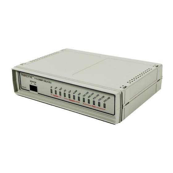
Model 7112 T1 SNMP DSU/CSU
Startup Instructions
Document Number 7112-A2-GN10-40
February 2000
Product Documentation on the World Wide Web
Package Checklist
7112-A2-GN10-40
We provide complete product documentation online. This lets you search the
documentation for specific topics and print only what you need, reducing the
waste of surplus printing. It also helps us maintain competitive prices for our
products.
Complete documentation for this product is available at www.paradyne.com.
Select Library
Technical Manuals
Select the following document:
7112-A2-GB20
Model 7112 T1 DSU/CSU, with Internal Ethernet LAN Adapter, User's Guide
To request a paper copy of a Paradyne document:
H
Within the U.S.A., call 1-800-PARADYNE (1-800-727-2396)
H
Outside the U.S.A., call 1-727-530-8623
Verify that your package contains the following in addition to the startup
instructions:
- A Model 7112 T1 DSU/CSU
- Wall-mount ac adapter
- One RJ48C unkeyed modular cable for T1 network
- One 8-position unkeyed modular cable for Ethernet LAN access
February 2000
Subrate Digital Access Devices.
1
Advertisement
Table of Contents

Related Manuals for Paradyne 7112


Summary of Contents for Paradyne 7112
-
Page 1: Package Checklist
Complete documentation for this product is available at www.paradyne.com. Select Library Select the following document: 7112-A2-GB20 Model 7112 T1 DSU/CSU, with Internal Ethernet LAN Adapter, User’s Guide To request a paper copy of a Paradyne document: Within the U.S.A., call 1-800-PARADYNE (1-800-727-2396) Outside the U.S.A., call 1-727-530-8623... -
Page 2: Cables You May Need To Order
Standard crossover EIA-232 cable with DB25 plug connectors on both ends. Standard straight-through V.35 cable with an MS34 plug connector on one end and an MS34 socket connector on the other end. Standard V.35 crossover cable with MS34 plug connectors on both ends. February 2000 7112-A2-GN10-40... - Page 3 6. Insert the other end of the cable into the Ethernet interface of the LAN where your NMS resides. 7. Plug the 25-pin end of an EIA-232 cable into the TERMINAL port of the DSU/CSU. 7112-A2-GN10-40 Power Connection Connection 10BaseT...
- Page 4 Configures your modem to raise LSD after establishing a connection. Configures your modem to drop connection when the DSU drops DTR. Configures your modem to raise DSR when it begins to establish a connection. Configures your modem to automatically answer incoming calls. February 2000 7112-A2-GN10-40...
- Page 5 NOTE: The Pin 17 to Pin 24 crossovers shown in Figure 1 are not required and have no effect with the Model 7112. Pin 14 Pin 1 Pin 13 Pin 25 Chassis Ground Signal Ground CD (RLSD) Figure 1. Serial Crossover Cable for External Modem...
-
Page 6: Hardware Verification
9.6 kbps, using characters of 8 bits, one stop bit, and no parity. Verifying the connection to a LAN, router, or external modem requires setup and configuration; see Chapter 3, Configuring the DSU/CSU, in the User’s Guide. 7112 SNMP DSU/CSU MONITOR System Network... - Page 7 Tables 2 through 8 list the DSU/CSU’s configuration options and the default values that have been preconfigured at the factory. Table 2. System Options Configuration Option Self Test Test Timeout Test Duration (min) 7112-A2-GN10-40 Settings (default in Bold) Enable, Disable Enable, Disable 1–120 February 2000 [10]...
- Page 8 Enable, Disable Disable, Enable < Blank > Settings (default in Bold) Block, ACAMI, Channel P(B) P(B) Settings (default in Bold) Nx64, Nx56 Enable, Disable Internal, External Enable, Disable None, Halt Disable, V.54, FT1, Both Disable, DTLB, DCLB, Both February 2000 7112-A2-GN10-40...
- Page 9 Table 8. Telnet Session Options Configuration Option Telnet Session Login Required Session Access Level Inactivity Timeout Disconnect Time (minutes) 7112-A2-GN10-40 Settings (default in Bold) 802.3, Version 2, Disable [000.000.000.000] – 255.255.255.255 [000.000.000.000] – 255.255.255.255 [000.000.000.000] – 255.255.255.255 Settings (default in Bold) 2.4, 4.8, 9.6, 14.4, 19.2, 28.8, 38.4...
- Page 10 1, 2, 3, 4, 5, 6, 7, 8, 9, 10 000.000.000.000 – 255.255.255.255 Read, Read/Write Enable, Disable 1, 2, 3, 4, 5, 6 000.000.000.000 – 255.255.255.255 None, Mgmt, FDL Disable, Warm, AuthFail, Both Enable, Disable Disable, Up, Down, Both Network, Port, Both February 2000 7112-A2-GN10-40...
-
Page 11: Important Safety Instructions
— Avoid using a telephone (other than a cordless type) during an electrical storm. There may be a remote risk of electric shock from lightning. — Do not use the telephone to report a gas leak in the vicinity of the leak. 7112-A2-GN10-40 February 2000... - Page 12 To Users of Digital Apparatus in Canada: This Class A digital apparatus meets all requirements of the Canadian interference-causing equipment regulations. Cet appareil numérique de la classe A respecte toutes les exigences du règlement sur le matérial brouilleur du Canada. February 2000 7112-A2-GN10-40...
-
Page 13: Government Requirements
6. No repairs may be performed by the user. Should you experience difficulty with this equipment, refer to Warranty, Sales, Service, and Training Information on page 14. 7112-A2-GN10-40 Description 1.544 Mbps superframe format (SF) without line power 1.544 Mbps SF and B8ZS without line power 1.544 Mbps ANSI ESF without line power... -
Page 14: Warranty, Sales, Service, And Training Information
Largo, FL 33773, or send e-mail to userdoc@paradyne.com. Include the number and title of this document in your correspondence. Please include your name and phone number if you are willing to provide additional clarification. *7112-A2-GN10-40* Copyright E 2000 Paradyne Corporation. Printed in U.S.A. *7112–A2–GN10–40*...
Need help?
Do you have a question about the 7112 and is the answer not in the manual?
Questions and answers