
Related Manuals for dental X Axyia 6


Summary of Contents for dental X Axyia 6
- Page 1 Water steam sterilizer 129A0150 129A0151 OPERATOR MANUAL USE and MAINTENANCE Axyia 6_DX17_UM_EN Rev. 09 Date: December 2020 OM1015EN...
-
Page 3: Table Of Contents
Description of the sterilizer ..................................11 Intended use ........................................11 Environmental conditions ...................................11 Units that make up the Axyia 6 sterilizer ...............................12 Units that make up the DX17 sterilizer ..............................13 Components supplied with the sterilizer ..............................15 Size and weight of the packaging ................................16 Size and weight of the sterilizers ................................17... - Page 4 TABLE OF CONTENTS 5.12 Diagnostics ........................................39 5.12.1 Manual diagnostics..................................... 39 5.12.2 Automatic diagnostics via Software ............................... 39 5.12.3 Demineralized water quality ..................................39 5.13 Connections ........................................40 5.13.1 Connection to an external printer ................................40 5.13.2 CUSTOM printer (optional) ..................................40 5.13.3 Connection to USB LOG 2.0 (optional) ..............................
-
Page 5: General Information
„ appropriate and safe use „ proper maintenance The manual is an integral part of the Axyia 6 and DX17 water steam sterilizers, hereafter referred to in this manual as: “sterilizer" or, more simply, "device", and must remain with them always, even when sold. -
Page 6: Professional User Profiles
Conformity with European Directives The Axyia 6 and DX17 sterilizers manufactured by NSK Dental Italy satisfies the essential requirements of the Directive 93/42/ EEC for medical devices, European Standard EN 13060 and Directive 2014/68/EC for pressure equipment (PED). -
Page 7: Safety Information
SAFETY INFORMATION - 2 SAFETY INFORMATION General safety information To maintain the highest level of device safety for patients and specialized professional operators, it is essential that: „ operators and maintainers have read and understood the instructions for use of the device; „... -
Page 8: List Of Safety And Protection Features On The Device
2.2.3 Overheating protection The Axyia 6 and DX17 sterilizers are equipped with a sophisticated self-diagnosis and process control system that checks whether the temperature and pressure parameters measured in the chamber are within the required limits and their ratio is correct to ensure steam saturation. -
Page 9: List Of Safety Signs On The Device
SAFETY INFORMATION - 2 List of safety signs on the device The following warning and hazard signs are located on the sterilizer in the positions indicated. Caution! Caution! Hot surfaces. Hot surfaces. 129A0150 Caution! Caution! Hot surfaces. Hot surfaces. 129A0151 Caution! Caution! Hot surfaces. -
Page 10: Residual Risks
SAFETY INFORMATION - 2 Residual risks The sterilization process works by means of pressurized steam at high temperature. When removing a load from the sterilization chamber, always use suitable tools and personal protective equipment for handling the hot racks and instruments. When opening the sterilizer door, particularly in the case of a cycle failure, a small quantity of steam or hot condensate may be released: open the door with caution. -
Page 11: Characteristics
CHARACTERISTICS Description of the sterilizer The Axyia 6/DX17 is a table-top water steam sterilizer designed for the sterilization of products and equipment for dental and medical use, according to the requirements of standard ISO EN 13060. It consists of a sealed steel sterilization chamber accessed via a door on the front; it is protected by a sheet steel external casing and equipped with protective devices that allow it to be used in complete safety by the operator. -
Page 12: Units That Make Up The Axyia 6 Sterilizer
CHARACTERISTICS - 3 Units that make up the Axyia 6 sterilizer 129A0153 129A0179... -
Page 13: Units That Make Up The Dx17 Sterilizer
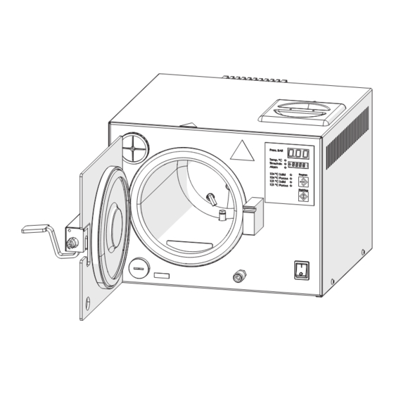
CHARACTERISTICS - 3 Units that make up the DX17 sterilizer 129A0154 129A0180... - Page 14 CHARACTERISTICS - 3 129A0152 Position Description Door Clean demineralized water tank cap Handle Operator control panel Main switch Aluminium sterilization chamber closure door disk Sterilization chamber Water filling inlet Chamber closure door gasket Clean demineralized water supply filter Air discharge Drain filter Temperature sensor Quick coupling for water tank drain...
-
Page 15: Components Supplied With The Sterilizer
CHARACTERISTICS - 3 Components supplied with the sterilizer 129A0178 Position Description Tray rack Tray 180 mm x 140 mm (3 pieces) Tray holder for insertion and extraction Rubber drain hose with quick coupling Water filter extraction key Water filter (2 pieces) Bacterial filter (1 piece) Operator Manual Warranty certificate... -
Page 16: Size And Weight Of The Packaging
CHARACTERISTICS - 3 Size and weight of the packaging Total package weight: 23.5 kg NOTE Keep the original packaging intact 475 mm 525 mm 375 mm 129A0175... -
Page 17: Size And Weight Of The Sterilizers
CHARACTERISTICS - 3 Size and weight of the sterilizers 129A0198 Size and weight of the sterilizer Axyia 6 DX17 STERILIZER 377 mm 303 mm 450 mm 435 mm 410 mm 395 mm 658 mm 701 mm 502 mm 498 mm... -
Page 18: Sterilizer Technical Data
CHARACTERISTICS - 3 Sterilizer technical data Technical data Axyia 6 DX17 Chamber dimensions Ø = 170 mm P = 276 mm Ø = 170 mm P = 276 mm Chamber volume 6.0 l 6.0 l 1.4 kg (solid instruments) 0.2 kg 1.4 kg (solid instruments) 0.2 kg... -
Page 19: Axyia 6 And Dx17 Sterilizer Identification Label
CHARACTERISTICS - 3 3.10 Axyia 6 and DX17 sterilizer regulatory label On the back of the sterilizer there is a nameplate with the CE marking, important operating data (already indicated in the Technical Data Table) and the serial number. For convenience, the serial number of the device is also displayed on an adhesive label affixed to the lower section of the inner front panel, which can be seen when the sterilization chamber door is open. - Page 20 CHARACTERISTICS - 3 The following table gives the meanings of the symbols displayed on the label: Symbol Manufacturer symbol. Manufacturer symbol. The data given next to this symbol identifies the manufacturer. NOTE: this symbol must be accompanied by the name and address of the manufacturer.
-
Page 21: Installation
INSTALLATION - 4 INSTALLATION Unpacking and transport The packaging of the sterilizer is composed of corrugated cardboard casing adequately protected by buffers. Place the packaging on a flat, uncluttered surface in order to open it easily and remove the sterilizer safely. „... -
Page 22: Positioning
INSTALLATION - 4 Positioning Ensure that the voltage of the electrical power supply to the device complies with the specifications on the nameplate located on the back panel, that the power socket is rated to provide at least 16A and that it is has an earth connection. -
Page 23: Initial Start-Up
INSTALLATION - 4 Initial start-up The following operations must be performed by qualified, properly trained personnel. Incorrect WARNING procedures and settings may impair the quality of the sterilization and cause injuries. „ Check that the power supply outlet has the correct voltage and connect the power cord to the outlet. - Page 24 INSTALLATION - 4 „ The first time the machine is started, the ALTITUDE 100 message appears on the display, indicating the request to enter the altitude of the autoclave’s location: press the PROGRAM or START/STOP buttons to enter and increase or decrease the altitude setting in metres.
-
Page 25: Compensating For Altitude
INSTALLATION - 4 Compensating for altitude The sterilizer microprocessor has an atmospheric pressure compensation function to ensure that the device operates correctly. During installation, or if the device is transferred to a place at a different altitude, the altitude value (in relation to sea level) must be set to that of the location where the device is used. -
Page 26: Setting Date And Time
INSTALLATION - 4 Setting Date and Time To access the setup menu, press the START/STOP and PROGRAM buttons at the same time for a few seconds; the SET TIME indication will appear on the lower display. Press the START/STOP and PROGRAM buttons at the same once more to access the menu. -
Page 27: Setting The Altitude
INSTALLATION - 4 Setting the altitude To access the setup menu, press the START/STOP and PROGRAM buttons at the same for a few seconds, scroll (decrease ) buttons individually until SET ALTITUDE through the following menus using the (increase ) or appears on the lower display. -
Page 28: Service And Default Factory Settings
INSTALLATION - 4 Service and Default Factory settings There are two menus, Technician and Factory, which can be accessed only by authorized technical personnel. They are protected by passwords to prevent accidental changes by the end user or unauthorized persons. TECH MENU: exclusively for technical support (password protected) NOTE FACTORY MENU: exclusively for use by the manufacturer (password protected) -
Page 29: Using The Sterilizer
5.1.1 Axyia 6 Operator Panel 1. Display Press. BAR, which shows the pressure (in bars) in the various phases of the selected work cycle. 2. Display Temp. °C; Time/min. ; Alarm, which displays alternately, in relation to the reference LED: the temperature (in °C) of the chosen work cycle;... - Page 30 USING THE STERILIZER - 5 5.1.2 DX 17 Operator Panel 1. Display Press. BAR, which shows the pressure (in bars) in the various phases of the selected work cycle. 2. Display Temp. °C; Time/min. ; Alarm, which displays alternately, in relation to the reference LED: the temperature (in °C) of the chosen work cycle;...
-
Page 31: Turning On The Sterilizer
USING THE STERILIZER - 5 Turning the sterilizer on Turn on the sterilizer with the main switch located on the operator control panel on the front. Switching on the device starts the pre-heating phase; in this phase the chamber temperature reaches and then remains at around 100°C. -
Page 32: Daily Sterilizer Performance Checks
USING THE STERILIZER - 5 Daily tests to check the sterilizer’s performance During the inspections carried out by the manufacturer, in accordance with regulations, the sterilizer is subjected to extensive testing and calibration checks. These tests guarantee the performance of the device, except for cases of unauthorized repairs, tampering or improper use. -
Page 33: Preparing The Material Before Sterilization
USING THE STERILIZER - 5 Preparing the material before Sterilization 5.4.1 Preliminary operations All the material to be prepared for sterilization is normally contaminated material. The following precautions must be taken before handling or moving contaminated material or equipment: „ Wear rubber or latex gloves of sufficient thickness and a facemask; „... -
Page 34: Arranging The Material On The Trays Before Sterilization
USING THE STERILIZER - 5 Arranging the material on the trays before sterilization Follow the guidelines below to obtain optimum effectiveness from the sterilization process and to preserve the life of the materials and instruments. Place a chemical sterilization indicator on each tray to avoid sterilizing the same load twice or NOTE using unsterilized material. -
Page 35: Program Selection
USING THE STERILIZER - 5 Program selection Depending on the degree of sterilization required, the operator has a selection of 4 types of programs, with a class S sterilization cycle, as described in Programs Table. To select the 134°C SOLID, 134°C POROUS, 121°C SOLID and 121°C POROUS programs, press the PROGRAM button a number of times until the desired program is highlighted. -
Page 36: Program Execution
USING THE STERILIZER - 5 Program execution Close the door by pushing the handle fully to the right and then down to run the selected program. Press START/STOP to start the cycle; for a few seconds the lower display will show the sequential number of the started cycle (e.g. -
Page 37: Opening The Door, Removing The Load, Report
USING THE STERILIZER - 5 Opening the Door, Removing the Load, Report The sterilization cycle of the selected program has finished and the load can be removed. To unlock and open the door, raise the handle and push it all the way to the left. The sterilized instruments and sterilization chamber are very hot. -
Page 38: Filling With Demineralized Water And Recycling The Used Water
USING THE STERILIZER - 5 5.11 Topping up with demineralized water and drawing contamined water The sterilizer is equipped with a 2-litre tank for demineralized water into which the recovered condensate from the used water is also conveyed. The hydraulic circuit provides reuse of the steam produced during the sterilization cycle (steam condensate), allowing lower water consumption through this configuration. -
Page 39: 5.12 Diagnostics
USING THE STERILIZER - 5 5.12 Diagnostics 5.12.1 Manual diagnostics Qualified operators (authorized technicians only) can perform diagnosis on the sterilizer by accessing the password- protected TECH MENU. The technician menu provides access for adjustment of the sterilization parameters. During diagnosis through the TECH MENU, sterilization loads must not be placed in the device. To NOTE perform cycles with loads, you must first exit the diagnostics phase by selecting one of the cycles in the selection menu on the control panel. -
Page 40: 5.13 Connections
USING THE STERILIZER - 5 5.13 Connections 5.13.1 Connection to an external printer The device does not have a built-in printer, but is designed for connection to an external printer, to which the process data is sent for documentation and certification of the sterilization. The use of a printer, mandatory in some countries, is becoming increasingly frequent to ensure the proper sterilization of dental material, also from a medico-legal perspective. -
Page 41: Connection To Usb Log 2.0 (Optional)
USING THE STERILIZER - 5 Replacing the paper • Open the lid by lifting the upper tabs; • Remove the empty roll and insert a new roll with the sensitive side of the paper facing upwards; • Use original chemical paper with a width of 57 mm and a Ø of 30 mm;... - Page 42 USING THE STERILIZER - 5...
-
Page 43: Alarms
ALARMS Overview The Axyia 6 and DX17 sterilizers have a sophisticated process control system that constantly checks the temperature and pressure parameters and their correct balance to ensure steam saturation. For any malfunction or fault, the cycle is interrupted, the red ALARM LED lights up and the incident is immediately signalled to the operator on the lower display through warning messages and alarm codes, accompanied by an acoustic signal. - Page 44 ALARMS - 6 MESSAGES ON CAUSE SOLUTION THE DISPLAY Check for water leaks and/or clean the door gasket. Check for any water leaks along the hoses and around the autoclave. Insufficient pressure SV unit (bistable solenoid valve) open or not working. LO PRE (appears only during the sterilization H2O loading pump dirty or not working.
- Page 45 ALARMS - 6 MESSAGES ON CAUSE SOLUTION THE DISPLAY Device too hot or too many consecutive cycles performed; turn off the device and wait for 10 minutes before processing further loads. Check for water leaks and/or clean the door gasket. Chamber temperature sensor overheating Check for any water leaks along the hoses and around the...
-
Page 46: Problems Without Warnings Or Alarms
ALARMS - 6 Problems without Warnings or Alarms PROBLEM CAUSE SOLUTION Main circuit board faulty or out of control. Cycle interrupted, overpressure THE SAFETY Check that the knurled locking ring on the safety valve is incident VALVE IS properly tightened. TRIGGERED (FAIL fault during cycle). -
Page 47: Maintenance
MAINTENANCE - 7 MAINTENANCE Periodic maintenance Maintenance of the device must be carried out by suitably trained personnel, who have read and understood all the procedures and information given in this Instruction Manual, particularly in CAUTION Chapter 2 on Safety. Always wear sterilized disposable latex gloves. -
Page 48: Cleaning The Sterilization Chamber
MAINTENANCE - 7 Cleaning the sterilization chamber Do not use abrasive products. Do not perform cleaning with the trays in the sterilization chamber. Clean the surfaces of the WARNING sterilization chamber when the device is cold. 1. Remove the rack and the trays from inside the sterilization chamber and wash them with a common neutral detergent. -
Page 49: Replacing The Bacterial Filter
MAINTENANCE - 7 Remove the filter 3, which is mounted directly on the holder 2. • • Clean the filter with compressed air (or ultrasound), or replace it with a new filter 3 if damaged. Refit the filter on the filter holder 2. •... -
Page 50: Scheduled Maintenance
4 Years/ 10,000 cycles *) Special maintenance must be performed by qualified personnel authorized by Dental X. If the sterilizer has to be returned or is taken away for repairs in a workshop or factory, remember to accompany it with a photocopy of the sales invoice and, in the case of returns, the required RMA, which should always be requested in advance from the Dental X Customer Care office before sending the device. - Page 52 A sales division of: A sales division of: NSK Dental Italy S.r.l. NSK Dental Italy S.r.l. Via dell‘Agricoltura, 21 36016 Thiene (VI) Italy Via dell‘Agricoltura, 21 36016 Thiene (VI) Italy Tel. +39 0444 367400 / +39 0445 820070 Tel. +39 0444 367400 / +39 0445 820070 e-mail: dentalx@dentalx.it / www.dentalx.it e-mail: dentalx@dentalx.it / www.dentalx.it...
Need help?
Do you have a question about the Axyia 6 and is the answer not in the manual?
Questions and answers