
Related Manuals for dental X dxp DOMINA PLUS B


Summary of Contents for dental X dxp DOMINA PLUS B
- Page 1 Steam sterilizer OPERATOR MANUAL USE and MAINTENANCE Domina Plus B_UM_EN Rev. 12 Date: October 2019 OM1004U...
-
Page 3: Table Of Contents
TABLE OF CONTENTS GENERAL INFORMATION ..................5 Purpose of the manual ....................................5 Criteria for use of the manual and finding information ........................5 Professional user profiles ....................................6 Conformity to European Directives ................................6 Warranty ..........................................6 SAFETY INFORMATION ..................7 General safety information ................................... - Page 4 TABLE OF CONTENTS 5.12 Connections ........................................36 5.12.1 Connection to an external printer ................................36 5.12.2 Integrated printer (optional) ..................................37 5.12.3 Connection to a USB log (optional) ................................. 37 ALARMS ......................38 Overview ...........................................38 List of warning messages ....................................38 List of alarms ........................................39 MAINTENANCE....................40 Periodic maintenance ....................................40 Sterilization chamber automatic cleaning cycle ..........................40...
-
Page 5: General Information
The company that uses the devices is responsible for always ensuring that all operators fully understand the operating instructions. DENTAL X declines any responsibility for failure to observe the safety and prevention rules described in the various sections of this manual and for damages caused by improper installation and use of the device. -
Page 6: Professional User Profiles
The Domina Plus B sterilizer produced by NSK Dental Italy satisfies the essential requirements of the Directive 93/42/EEC for medical devices, European Standard EN 13060 and Directive 2014/68/EC for pressure equipment (PED). This DENTAL X product has been designed and manufactured with high quality materials and parts that can be recycled and reused. -
Page 7: Safety Information
SAFETY INFORMATION - 2 SAFETY INFORMATION General safety information To maintain a maximum level of device safety for patients and specialized professional operators, it is essential that: „ the operators and maintenance technicians have read and understood the instructions for installation and use of the device „... -
Page 8: Safety And Protection Features On The Device
SAFETY INFORMATION - 2 Safety and protection features on the device The sterilizer has several devices, listed below, that ensure the total safety of operators. 2.2.1 Soft-close door with double safety An electromechanical device allows the door to be opened only under the following conditions: •... -
Page 9: Safety Signs On The Device
SAFETY INFORMATION - 2 Safety signs on the device The following warning and hazard signs are located on the sterilizer in the positions indicated. Caution! Hot surfaces. Caution! Do not sterilize fluids. Caution! Service port for downloading data. Do not connect to the Internet. -
Page 10: Residual Risks
SAFETY INFORMATION - 2 Residual risks The sterilization process works by means of pressurized steam at high temperature. When removing a load from the sterilization chamber, always use suitable tools and personal protective equipment for handling the hot racks and tools. When opening the sterilizer door, particularly during a cycle failure, a small quantity of steam or hot condensate may be released;... -
Page 11: Characteristics
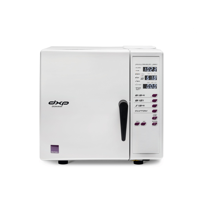
CHARACTERISTICS - 3 CHARACTERISTICS Description of the sterilizer The Domina Plus B is a table-top steam sterilizer designed for the sterilization of dental and medical products and equipment, in accordance with the requirements of standard ISO EN 13060. It consists of an airtight copper sterilization chamber accessed through a front door; it is protected by an external shock- resistant moulded plastic body and equipped with protective devices that allow operators to use it in full safety. -
Page 12: Units That Make Up The Sterilizer
CHARACTERISTICS - 3 Units that make up the sterilizer... - Page 13 CHARACTERISTICS - 3 Position Description Door Clean demineralized water tank input Handle Operator panel Printer (optional) Steel sterilizing chamber closure disc Bacteriological filter Sterilization chamber Clean demineralized water tank filter Drain filter Quick coupling for draining contaminated water tank Quick coupling for draining demineralized water tank Network port for technical support service data Temperature sensor Safety valve connection...
-
Page 14: Components Supplied With The Sterilizer
CHARACTERISTICS - 3 Components supplied with the sterilizer Position Description Tray rack Small tray (2 pieces) Large tray (2 pieces) Rack insertion and extraction clamp Rubber hose with quick coupling for draining water Water filter extraction key Water filter (2 pieces) Bacteriological filter Sterilization chamber cleaning tablets (2 pieces) Operator manual... -
Page 15: Size And Weight Of Package
CHARACTERISTICS - 3 Size and weight of package Packaging size: 720 x 600 x 530 mm (L x H x D) Total weight of package: 55 kg NOTE Keep the original packaging intact Size and weight of sterilizer STERILIZER Net unladen weight: 45 kg Weight with full load: 57 kg... -
Page 16: Technical Specifications
CHARACTERISTICS - 3 Technical specifications Chamber dimensions Ø = 240 mm D = 384 mm Chamber volume 17.5 l Maximum load 4 kg (solid instruments) 1.5 kg (porous instruments) Heating time 20’ from room temperature 10’ with preheated chamber Sterilization time From 3’... -
Page 17: Sterilizer Regulatory Label
CHARACTERISTICS - 3 Sterilizer regulatory label The regulatory label is fixed on the back of the sterilizer and displays the CE marking together with important data for operation, already given in the technical specifications table, and the serial number. For convenience, the device serial number is also displayed on an adhesive label on the lower section of the internal front panel, visible when the sterilization chamber door is open. - Page 18 CHARACTERISTICS - 3 Symbol Description Symbol for manufacturer. The data given next to this symbol identifies the manufacturer. NOTE: this symbol must be accompanied by the name and address of the manufacturer. NSK Dental Italy S.r.l. Manufacturer's name Via dell’Agricoltura 21, 36016 Thiene (VI) IT Manufacturer’s address Manufacturing company’s logo CE marking in accordance with Dir.
- Page 19 CHARACTERISTICS - 3 Caution, carefully read the instructions for use before using the device. Symbol for separate waste collection of electrical and electronic devices, in conformity with Directive 2012/19/EU (WEEE/RAEE).
-
Page 20: Installation
INSTALLATION - 4 INSTALLATION Unpacking and transportation The packaging of the sterilizer consists of a wooden pallet on which the sterilizer is placed, with adequate protective padding and a corrugated cardboard casing fixed to the pallet with metal staples. Place the package on a level surface free from clutter to facilitate easy opening and safe extraction of the sterilizer. „... -
Page 21: Positioning
INSTALLATION - 4 Positioning Check that the power supply voltage to the device matches that shown on the regulatory label on the rear panel, that the power outlet is designed to supply at least 16A and that it has an earth connection. If the installation makes the main power switch inaccessible, a specially dedicated accessible electrical disconnection switch should be provided. - Page 22 INSTALLATION - 4 In the case of built-in installation with a shelf above the device, a space of at least 2-3 cm should be left between the bottom of the shelf and the top of the device. Place the device on a mobile shelf with a sliding rail extraction system to allow filling of the deionized water tank, positioned on the top, and access to the main switch at the back of the device.
-
Page 23: Initial Start-Up
INSTALLATION - 4 Initial start-up The following operations must be carried out by qualified and properly trained personnel. WARNING Incorrect procedures and settings can jeopardize the quality of sterilization and cause hazards. „ Check that the power supply has the right voltage and plug the power cord into the outlet. -
Page 24: Compensating For Altitude
INSTALLATION - 4 „ Press the button and the POWER button at the same time. The message SET ALT 100 MT appears on the display, showing the default altitude setting (100 m a.s.l.). „ Using the or buttons, adjust the setting to the actual altitude of the installation site (see paragraph on “Compensating for altitude”). -
Page 25: Setting Date And Time
INSTALLATION - 4 Setting date and time To access the date and time settings, press the SET button. Each time the SET button is pressed, a different specific function is displayed. The settings for each function can be changed by pressing the and buttons. The functions accessed by repeatedly pressing the SET button are described in the following table. -
Page 26: Using The Sterilizer
USING THE STERILIZER - 5 USING THE STERILIZER Description of the operator panel The operator panel, located on the right-hand side of the front panel, allows the operator to receive information and to give all types of commands necessary for proper operation of the sterilizer. It consists of: an alphanumeric display, LED indicators, function buttons and an optional printer, described in detail below. -
Page 27: Turning The Sterilizer On
USING THE STERILIZER - 5 Turning the sterilizer on Turn the sterilizer on using the main switch on the back of the device. • The TIME display shows the current time • The TEMP display indicates OFF • The PRESS display shows the date and month Press the POWER button and wait a few seconds for completion of the automatic self-test. -
Page 28: Preparing The Material Before Sterilization
USING THE STERILIZER - 5 Preparing the material before sterilization 5.4.1 Preliminary operations All the material to be prepared for sterilization is normally contaminated. Before handling or moving contaminated materials or instruments, the following precautions should be taken: „ Wear rubber or latex gloves of suitable thickness and a face mask; „... -
Page 29: Arranging The Material On The Trays Before Sterilization
USING THE STERILIZER - 5 Arranging the material on the trays before sterilization Follow the guidelines below to obtain optimum effectiveness from the sterilization process and to preserve the life of the materials and instruments. Place a chemical sterilization indicator on each tray to avoid sterilising the same load twice or using NOTE unsterilized material. -
Page 30: Program Selection
USING THE STERILIZER - 5 Program selection Various types of programs are available to the operator, depending on the degree of sterilization desired, with a class B or class S sterilization cycle, as described in the program table. To select programs B134, B121 and S134, press the corresponding button on the operator panel. To select one of the CUSTOM programs, press the CUSTOM button on the operator panel, then the ... -
Page 31: Running The Program
USING THE STERILIZER - 5 Running the program Press the START/STOP button to run the selected program. The S134 programs are CUSTOM programs and not guarantee class B sterilization. To run these types of NOTE programs, press and hold the S134 or CUSTOM button and press the key START/STOP button. When the program starts, the door is locked and remains locked for the entire duration of the program. -
Page 32: Interrupting The Programme
USING THE STERILIZER - 5 At the end of the S134, CUSTOM S1 and CUSTOM S5 cycles, only the READY LED lights up, without the STERILIZE LED, to indicate that the set cycle does not ensure class B sterilization; the display shows the CAUTION sequence of cycles. -
Page 33: Setting The Custom - S5 Program
USING THE STERILIZER - 5 Setting the CUSTOM - S5 program The CUSTOM - S5 program is the only one that can be customized by the operator. To access the S5 program setting functions, press the SET button and then the CUSTOM button. Each time the SET button is pressed, a different specific function is displayed, which can be changed by pressing the ... -
Page 34: Topping Up With Demineralized Water And Draining Contaminated Water
USING THE STERILIZER - 5 5.10 Topping up with demineralized water and draining contaminated water The sterilizer is fitted with two 4-litre tanks: the main demineralized water tank and the contaminated water recovery tank. The hydraulic circuit does not allow the reuse of the steam produced during the sterilization cycle, which is collected in the recovery tank and must be periodically drained. -
Page 35: Diagnostics
USING THE STERILIZER - 5 5.11 Diagnostics 5.11.1 Manual diagnostics A qualified operator may perform a diagnostic test on the sterilizer at any time using the procedure described in the following table PHASE 1 Steps to perform Indications on the displays Press the SET and TEST buttons in The three respective displays show: TEST, chamber temperature and chamber sequence... -
Page 36: Connections
USING THE STERILIZER - 5 A negative result from this check does not prevent use of the sterilizer; however, it is recommended CAUTION to replace demineralized water of less-than-ideal quality with better quality water. The following table shows the recommended minimum parameters for the water to be used Pollutants Supply water Condensate... -
Page 37: Integrated Printer (Optional)
USING THE STERILIZER - 5 To set the operation of the CUSTOM printer from the sterilizer operator panel, proceed as follows: • simultaneously press the S134 and CUSTOM buttons to enter the menu; • scroll the menu using the button, till PRINTER TYPE is displayed; •... -
Page 38: Alarms
ALARMS - 6 ALARMS Overview When the device is switched on and during each sterilization cycle, the characteristic parameters of the various phases of the cycle are constantly monitored, together with the proper functioning and perfect condition of all the components. Any anomaly or fault is immediately indicated on the display through warning messages and alarm codes, together with an acoustic signal. -
Page 39: List Of Alarms
ALARMS - 6 List of alarms ALARM CODE CAUSE SOLUTION cd 1 Clogged drain filter. Clean or replace filter. Run a cycle with a smaller load. If the problem cd 2 Slow heating of the upper part of the chamber. persists, contact the technical support service. -
Page 40: Maintenance
MAINTENANCE - 7 MAINTENANCE Periodic maintenance Maintenance of the device must be carried out by suitably trained personnel, who have read and understood all the procedures and information given in this instruction manual, particularly in CAUTION chapter 2 “Safety information”. Always wear sterilized disposable latex gloves. -
Page 41: Cleaning Or Replacement Of The Demineralized Water Filter
MAINTENANCE - 7 2. Place a cleaning tablet in the sterilization chamber and close the door. 3. Place the device in stand-by with the POWER button (OFF indicated on the display). 4. Press the START and the POWER buttons at the same time to start the automatic cleaning cycle. -
Page 42: Replacing The Bacteriological Filter
(RMA), which must always be requested in advance from the Dental X customer care office before sending the device. - Page 44 A sales division of: NSK Dental Italy S.r.l. Via dell’Agricoltura, 21 - 36016 Thiene (VI) - Italy Tel. +39 0445 820070 dentalx@dentalx.it - www.dentalx.it...
Need help?
Do you have a question about the dxp DOMINA PLUS B and is the answer not in the manual?
Questions and answers