Table of Contents
Troubleshooting

Related Manuals for ACEUP ENERGY AI4500


Summary of Contents for ACEUP ENERGY AI4500
- Page 1 PORTABLE GENERATOR 3 6 0 0 R U N N IN W A T T S 4 5 0 0 ST A R T IN W A T T S D Y RV R EA EL L IN K PA RA LL O...
-
Page 2: Table Of Contents
Table of Contents Section 1 Introduction and Safety ..................................Introduction ...................... Safety Rules ................Safety Symbols and Meanings ................Exhaust and Location Hazards ....................Electrical Hazards ....................... Fire Hazards ................... Replacement Hazard Labels Section 2 General Information and Setup ............ -
Page 3: Section 1 Introduction And Safety
Section 1 Introduction and Safety Introduction WARNING WARNING Consult Manual. Read and understand manual Indicates a hazardous situation which, if not avoided, completely before using product. Failure to could result in death or serious injury. completely understand manual and product could result in death or serious injury. -
Page 4: Exhaust And Location Hazards
DANGER Exhaust and Location Hazards Electrocution. Water contact with a power source, if not avoided, will result in death or serious injury. DANGER DANGER Asphyxiation. Running engines produce carbon monoxide, a colorless, odorless, poisonous gas. Electrocution. Turn utility and emergency power Carbon monoxide, if not avoided, will result in supplies to OFF before connecting power source death or serious injury. -
Page 5: Fire Hazards
Replacement Hazard Labels • National Electric Code (NEC) requires the frame and external electrically conductive parts of the Vertical CO Warning Decal generator be properly connected to an approved earth ground. Local electrical codes may also require proper grounding of the generator. Consult with a local electrician for grounding requirements in the area. -
Page 6: Section 2 General Information And Setup
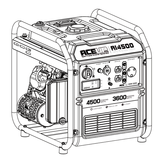
Section 2 General Information and Setup TABLE 1. Generator Components Figure 2-1. Features and Controls Figure 2-2. Control Panel Recoil Starter DC Breaker Grounding Lug 12 Volt DC Gas valve 20A Volt AC Sock Oil Drain AC Breaker Oil Fill 30A Volt AC Sock Fuel Tank Gauge Meter... - Page 7 Figure 2-3. Intelligent Gauge Six mode digital meter for displaying voltage, frequency, total run time, low oil alarm, power output, economic mode and AC reset. 1. V.F.R - Display voltage(V), frequency(H) and total run time(R) of inverter generator. 2. AC Reset Button - re-energize receptacles after overload fault. AC Reset Button - Switch voltage(V), frequency(H) and total run time(R) when not overloaded.
-
Page 8: Emissions
Emissions The United States Environmental Protection Agency (US EPA) (and California Air Resources Board (CARB), for engines/equipment certified to California standards) requires that this engine/equip- ment complies with exhaust and evaporative emissions standards. Locate the emissions compliance decal on the engine to determine applicable standards. -
Page 9: Connection Plugs
Owner's Manual for Petrol Generator Connection Plugs ON/OFF/CHOKE Switch This controls the ON/OFF functions, choke 120 VAC, 20 Amp, Duplex and fuel valve operation. See Figure 2-5. Receptacle • The OFF position (1) stops the engine and shuts off fuel flow. •... -
Page 10: Remove Contents From Carton
Owner's Manual for Petrol Generator If this occurs, disconnect all electrical loads to NOTE: The generator is shipped without oil in the engine. Add oil slowly and verify oil level determine the cause of the problem before often during filling process to ensure overfilling using the generator again. -
Page 11: Add Engine Oil
Owner's Manual for Petrol Generator Figure 2-9.Fuel Cap Figure 2-8. Safe Operating Range 4. Turn cap slowly to remove. 7. Remove dipstick and verify oil level is within safe operating range. 5. Slowly add recommended fuel. Do not overfill. NOTE: Verify oil level often during filling pro- 6. -
Page 12: Section 3 Operation
Owner's Manual for Petrol Generator Before Starting Engine Grounding the Generator When 1. Verify engine oil level is correct. In Use 2. Verify fuel level is correct. The generator is equipped with an equipment 3. Verify unit is secure on level ground, with ground connecting the generator frame and proper clearance and is in a well ventilated the ground terminals on the AC output recep-... -
Page 14: Low Oil Level Shutdown System
Owner's Manual for Petrol Generator Figure 3-2. When engine starts, rotate 4. Follow Generator Shut Down instructions. OFF/ON/CHOKE dial to ON (2).CHOKE NOTE: For inverters, load applied to the paral- lel kit is not to exceed 3420 watts due to a operation reduced OFF/ON/-... -
Page 15: Section 4 Maintenance And Troubleshooting
Owner's Manual for Petrol Generator Maintenance Preventive Maintenance Regular maintenance will improve perfor- Dirt or debris can cause improper operation mance and extend engine/equipment life. and equipment damage. Clean generator We recommends that all maintenance work daily or before each use. Keep area around be performed by an Independent Autho- and behind muffler free from combustible... - Page 16 Owner's Manual for Petrol Generator 7. Replace oil fill cap and hand-tighten. NOTE: Some units have more than one oil fill location. It is only necessary to use one oil fill SAE 30 point. 10W-30 Change Engine Oil Synthetic 5W-30 WARNING Accidental start-up.
-
Page 17: Inspect Muffler And Spark Arrestor
Owner's Manual for Petrol Generator 9. To check oil level, remove funnel and insert dipstick into oil filler neck without screwing it in. See Figure 4-2. 10. Remove dipstick and verify oil level is within safe operating range. NOTE: Verify oil level often during filling pro- cess to ensure overfilling does not occur. -
Page 18: Storage
Owner's Manual for Petrol Generator 4. Replace the screens, and retainer, and Prepare Fuel System/Engine for secure with clamp. Storage Fuel stored over 30 days can go bad and damage fuel system components. Keep fuel fresh, use fuel stabilizer. If fuel stabilizer is added to fuel system, pre- pare and run engine for long term storage. -
Page 19: Troubleshooting
Owner's Manual for Petrol Generator Troubleshooting PROBLEM CAUSE CORRECTION Engine won't start. 1. Dial turned off. 1. Turn on Dial. 2. Out of fuel. 2. Fill fuel tank. 3. Defective spark plug. 3. Replace spark plug. 4. Plugged fuel filter. 4.
Need help?
Do you have a question about the AI4500 and is the answer not in the manual?
Questions and answers
CAN YOU USE 10W-30 OIL ALL THE TIME SYNTHETIC
Yes, 10W-30 synthetic oil can be used in the ACEUP ENERGY AI4500 generator.
This answer is automatically generated
WERE IS THE DRAIN OIL PLUG LOCATED ON A ACEUP 4500 GENERATOR INVERTED 223CC