Table of Contents
Advertisement
Quick Links
Advertisement
Table of Contents

Related Manuals for EL-CELL PAT-Tester-i-16

Summary of Contents for EL-CELL PAT-Tester-i-16
- Page 1 © 2016 EL-CELL GmbH User Manual Release 1.0 PAT-Tester-i-16 © 2024 EL-Cell GmbH...
- Page 2 EL-Cell GmbH makes no assurances or warranties concerning this manual and, to the extent permitted by law, limits its liability for violation of any implied warranty to the substitution of this manual for another. In addition, EL-Cell GmbH reserves the right to revise this publication at any time without notice to anyone.
- Page 3 PAT-Tester-i-16 User Manual Manufacturer and Customer Service EL-Cell GmbH Tempowerkring 8 21079 Hamburg Germany Telephone: +49 40 79012-734 Telefax: +49 40 79012-736 Email: info@el-cell.com Website: el-cell.com Technical Support Telephone: +49 40 79012-734 Email: support@el-cell.com Website: el-cell.com/support/technical-support/ Please always quote the serial number on the nameplate when contacting customer service.
-
Page 4: Table Of Contents
PAT-Tester-i-16 User Manual Content Preamble ............................... 7 Purpose and Target Audience ....................... 7 Storage Instructions ......................... 7 Obtaining Documents and Information..................7 For Your Safety ............................8 Explanation of the Safety Instructions ..................8 2.1.1 Terms used ............................. 8 2.1.2 Symbols used .......................... - Page 5 Installation ............................25 4.3.1 Minimum Space Requirement ....................25 4.3.2 Air Ventilation ..........................26 Start-up ............................... 27 Connecting the PAT-Tester-i-16 ....................27 5.1.1 Switching on and off ......................... 27 Operation and Control ..........................28 Display ............................... 28 6.1.1 Information on the LC Display ....................29 Opening the Lid ..........................
- Page 6 PAT-Tester-i-16 User Manual Storage .............................. 43 Disposal ............................. 43 Warranty ..............................44 Page 6 of 44 Release 1.0...
-
Page 7: Preamble
16. It is intended for the end users of the device. An end user can be described as any person who interacts directly with the PAT-Tester-i-16. The term "end user" usually includes laboratory personnel trained to operate this instrument and familiar with all the precautions required to work in the laboratory. -
Page 8: For Your Safety
PAT-Tester-i-16 User Manual 2 For Your Safety 2.1 Explanation of the Safety Instructions Specific recurring terms and symbols are used in these instructions and on the appliance to warn you of dangers or to give you essential information to prevent injury and damage. -
Page 9: Symbols Used
PAT-Tester-i-16 User Manual 2.1.2 Symbols used Warning symbols (warn of a danger) Danger of electric shock Hot surface Mandatory signs (prescribe an action) Wear gloves Pull out the mains plug Page 9 of 44 Release 1.0... -
Page 10: Product Safety And Hazards
PAT-Tester-i-16 User Manual 2.2 Product Safety and Hazards The device described is technically mature, is manufactured using high -quality materials, and is tested in the factory before delivery. It corresponds to the state of the art and the recognized safety regulations. Nevertheless, it still poses risks even wh en used as intended. -
Page 11: Position Of The Safety Symbols On The Product
PAT-Tester-i-16 User Manual 2.2.1 Position of the Safety Symbols on the Product 2.2.2 Requirements for the Operating Personnel The appliance may only be operated and maintained by persons of legal minimum age who have been instructed in its use. Personnel to be trained, instructed , or undergoing general training may only work on this appliance under the constant supervision of an experienced person. -
Page 12: Responsibility Of The Owner
Other uses can lead to danger and damage. NOTE The PAT-Tester-i-16 may only be used with test cells of the PAT series. Other cell types must be used with the adapters supplied by EL-CELL. Do not place any other objects in the cell chamber. -
Page 13: How To React In The Event Of Faults And Irregularities
2.6 How to React in the Event of Faults and Irregularities As the operator, you may only operate the PAT-Tester-i-16 if it is in perfect working order. If you, notice irregularities, faults, or damage, take the appliance out of operation immediately and inform your supervisor. -
Page 14: Structure And Description Of The Device
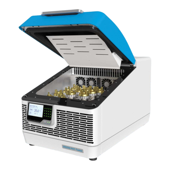
PAT-Tester-i-16 User Manual 3 Structure and Description of the Device LC display, control LEDs, and function button Temperature-controlled cell chamber Cell connections (PAT socket) Interior fan Cover Fan of the automatic venting system Type plate Page 14 of 44 Release 1.0... -
Page 15: Description Of The Device
16 sockets for PAT system test cells. Other cell types must be connected using the adapters available from the manufacturer. The PAT-Tester-i-16 has an internal control PC that stores the test data. This data can be retrieved and processed via the existing network interface. The EL -Software control software is supplied for this purpose. -
Page 16: Usb Connection
PAT-Tester-i-16 User Manual 3.2.2 USB Connection The USB connection is used for diagnostic purposes and to change the static IP of the device. This change is made using the EL-Software control software. The steps required to change the IP are described in the EL-Software manual. -
Page 17: Technical Data
PAT-Tester-i-16 User Manual 3.4 Technical Data 3.4.1 Dimensions Weight 26 kg (without test cells) Height approx. 600 mm/375 mm (opened/closed cover) Length 640 mm Depth 380 mm 3.4.2 General Device Data Device name PAT-Tester-i-16 Type Potentiostat/Galvanostat/Impedance Analyser with integrated temperature chamber Temperature chamber 10 to 80°C... -
Page 18: Performance Data Of The Individual Test Channels
PAT-Tester-i-16 User Manual 3.4.3 Performance Data of the Individual Test Channels General -7 to +7 V Control Voltage -8 V to +8 V (no load) Compliance Voltage ±100 mA Current 3 electrodes plus sense wires, Connection matrix Cell and electrode connections... - Page 19 PAT-Tester-i-16 User Manual <100 nA @ 10mA <10 nA @ 1mA <1 nA @ 100μA ±0.05% FSR Measurement Accuracy 1 nA min. (18 Bit) Control Resolution Impedance (each channel) Frequency range 100 μHz to 100 kHz Impedance mode PEIS and GEIS (simultaneous measurement of...
-
Page 20: Applied Guidelines And Standards
PAT-Tester-i-16 User Manual 3.5 Applied Guidelines and Standards The product described is in conformity with the following harmonized standards: EN 61010-1:2010 Sicherheitsbestimmungen für elektrische Mess-, Steuer-, Regel- und Laborgeräte – Teil 1: Allgemeine Anforderungen (DIN EN 61010-1, VDE 0411-1:2011-07) Safety requirements for electrical equipment for... - Page 21 PAT-Tester-i-16 User Manual (IEC 61326-2-3:2012) EN 61326-2-3:2013-07 Elektrische Mess-, Steuer-, Regel- und Laborgeräte - EMV- Anforderungen - Teil 2-3: Besondere Anforderungen - Prüfanordnung, Betriebsbedingungen und Leistungsmerkmale für Messgrößenumformer mit integrierter oder abgesetzter Signalaufbereitung (DIN EN 61326-2-3:2013-07, VDE 0843-20-2-3:2013-07) Electrical equipment for measurement, control and laboratory...
- Page 22 PAT-Tester-i-16 User Manual Page 22 of 44 Release 1.0...
-
Page 23: Delivery And Installation
PAT-Tester-i-16 User Manual 4 Delivery and Installation 4.1 Delivery The PAT-Tester-i-16 is packed in a cardboard box and delivered on a wooden pallet. 4.2 Unpacking To avoid damage, do not unpack the device until it is at its installation location. -
Page 24: Checking The Delivery For Completeness And Transport Damage
PAT-Tester-i-16 User Manual 4.2.2 Checking the Delivery for Completeness and Transport Damage Check that the scope of delivery is complete using the delivery note • Check the appliance for damage. • If you notice any deviations from the scope of delivery or damage, please inform the carrier and the manufacturer 4.2.3 Recycling the Packaging Material... -
Page 25: Installation
(see technical data). A power connection must be available at the installation site. 4.3.1 Minimum Space Requirement The PAT-Tester-i-16 requires at least the following space (device dimensions plus required clearances) for installation: Depth: min. 740mm Width: min. 380mm Height: min. -
Page 26: Air Ventilation
PAT-Tester-i-16 User Manual 4.3.2 Air Ventilation Sufficient air circulation in the vicinity of the appliance must be ensured at all times. Make sure that the air inlets and outlets on the front and rear of the PAT -Tester-i-16 are not covered. -
Page 27: Start-Up
• 5.1.1 Switching on and off The PAT-Tester-i-16 switches on as soon as it is connected to the power supply. To switch it off, simply disconnect the appliance from the power supply. Page 27 of 44... -
Page 28: Operation And Control
PAT-Tester-i-16 User Manual 6 Operation and Control The PAT-Tester-i-16, in particular, the temperature control of the cell chamber, is operated via the EL-Software control software. Further information on setting up and operating EL - Software can be found in the corresponding manuals, which can be downloaded from the website (https://el-cell.com/support/manuals). -
Page 29: Information On The Lc Display
PAT-Tester-i-16 User Manual 6.1.1 Information on the LC Display The views of the LC display can be changed using the selection button. They provide the following Information: 6.1.1.1 LC Display: View 1 (Standard View) Name of the device (the current device status can also be displayed here instead) - Page 30 PWM Heater Heating power of the heating wire (in the cell chamber) in percent (0..100%). Humidity Menu Only accessible by EL-CELL technicians for diagnostic purposes Firmware Currently installed firmware In certain situations, simultaneous heating and cooling can be displayed. This is used for dehumidification, where the Peltier elements serve as a cold trap.
-
Page 31: Opening The Lid
6.3 Inserting and Removing Test Cells The PAT-Tester-i-16 has 16 sockets for inserting PAT series battery test cells. Other cell formats can be connected to the PAT-Tester-i-16 using the adapters available from the manufacturer. -
Page 32: Inserting A Pat Series Test Cell
PAT-Tester-i-16 User Manual 6.3.1 Inserting a PAT Series Test Cell To insert the cell, insert it into the PAT socket until you hear the latch click into place. Only then is electrical contact guaranteed. 6.3.2 Removing a PAT Series Test Cell To remove a cell, press the silver button next to the PAT socket to release the lock (1) and remove the cell (2). -
Page 33: Faults, Warning And Error Messages
Disconnect the mains plug before removing any covers. Only qualified electricians may work on the electrical equipment of the appliances. Do not attempt to rectify device faults, but contact EL-Cell GmbH technical customer service. 7.1 Explanation of the Acoustic and Visual Signals 7.1.1 Visual Signals from the Test Channel LEDs... -
Page 34: Visual Signals On The Display
PAT-Tester-i-16 User Manual 7.1.2 Visual Signals on the Display 7.1.2.1 Error Codes This list shows the error codes that may appear on the PAT-Tester-i-16 display. Please state the error code in your message to our technical customer service. Error Code Meaning... - Page 35 PAT-Tester-i-16 User Manual 7.1.2.2 Status Messages Status messages can appear in the top line of the LC display instead of the device name. They provide information about the current operating status. They can also contain prompts for the operating personnel.
-
Page 36: Acoustic Signals
PAT-Tester-i-16 User Manual 7.1.3 Acoustic Signals Acoustic signals Meaning Beep once every 10 seconds (increasing Sounds as long as the lid to the cell chamber beep duration from 20ms to 500ms) is open. Close the lid. 7.1.4 Network Failure In the event of a network failure, the connection between the device and the EL -Software server is interrupted. -
Page 37: Maintenance And Repair
8 Maintenance and Repair 8.1 Cleaning Wipe the PAT-Tester-i-16 with a damp cloth. Do not use aggressive chemicals for cleaning. The metal surfaces inside the device can be cleaned with commercially available stainless steel cleaning agents. Suppose rust spots appear on the surface of the interior due to soiling. In that case, the affected areas must be cleaned and polished immediately. -
Page 38: Removing And Adding A Channel Board
PAT-Tester-i-16 User Manual 8.2 Removing and Adding a Channel Board The PAT-Tester-i-16 can be equipped with up to 16 test channels. The electronics of each channel are located on a separate circuit board (channel board). Follow the steps below to... -
Page 39: Installing A Channel Board
PAT-Tester-i-16 User Manual 8.2.1 Installing a Channel Board Turn the PAT-Tester-i-16 upright. Ensure the cover is closed and locked; otherwise, it may swing open and be damaged. Remove the two screws on the underside of the device. Now carefully tilt the underside downwards. - Page 40 PAT-Tester-i-16 User Manual Carefully insert the channel board. Ensure the connector on the back is correctly connected to the main board. Secure the channel board with the four retaining screws. Ensure that these are only hand-tightened. Close the housing again and secure the underside with the two screws.
-
Page 41: Removing A Channel Board
PAT-Tester-i-16 User Manual 8.2.2 Removing a Channel Board Turn the PAT-Tester-i-16 upright. Ensure the cover is closed and locked; otherwise, it may swing open and be damaged. Remove the two screws on the underside of the device. Now carefully tilt the underside downwards. - Page 42 PAT-Tester-i-16 User Manual Remove the four retaining screws at the corners of the channel board using a T10 Torx screwdriver. Make sure that no screws accidentally fall into the housing. Each channel board has a flat recess at the top and bottom. Insert a flat object, e.g., the corner of a plastic...
-
Page 43: Storage And Disposal
PAT-Tester-i-16 User Manual 9 Storage and Disposal 9.1 Storage The device may only be stored under the following conditions: dry and in a closed, dust-free room • frost-free • disconnected from the power supply • 9.2 Disposal The appliance must not be disposed of with regular household waste. Observe the applicable legal regulations. - Page 44 PAT-Tester-i-16 User Manual 10 Warranty For a period of one year from the date of shipment, EL-Cell GmbH (hereinafter Seller) warrants the goods to be free from defect in material and workmanship to the original purchaser. During the warranty period, Seller agrees to repair or replace defective and/or nonconforming goods or parts without charge for material or labor, or, at the Seller’s option, demand return...
Need help?
Do you have a question about the PAT-Tester-i-16 and is the answer not in the manual?
Questions and answers