Advertisement
Quick Links
Advertisement

Related Manuals for DoAll FLYWAY 80


Summary of Contents for DoAll FLYWAY 80
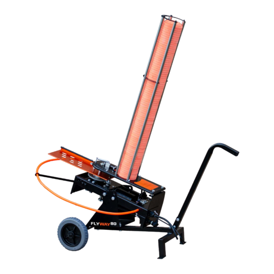
- Page 1 FLYWAY...
-
Page 2: Included Parts
INCLUDED PARTS Cart and Axle Assembly Hardware: Total of (7) Bolts, Cart Assembly (14) Washers, and (7) Nuts. Trap Head Base with (4) M10X15 Bolts and (4) plastic washers to connect Trap Head to Base Cart Axle & (4) Washers, (2) Spacers, and (2) “C”... - Page 3 STEP 1 Begin by flipping the Trap Head upside down. First, thread in the studs for the safety ring, which thread, by hand, from the outside in on each side of the rear of the trap, as shown above.
- Page 4 STEP 2 While the trap is still upside down, install the Front Leg Brackets and Safety Ring Arms (pointing forward, in the direction that the arm will throw the clays) using the (4) provided allen head screws. Secure the bolts with a 4mm alen wrench.
- Page 5 Front STEP 3 While the trap is still upside down, attach the Trap Head to the Trap Head Base using the (4) M10X15MM bolts and (4) plastic washers. (In order: Bolt, trap base, washer, trap head)
- Page 6 STEP 4 While the trap is still upside down, install the Cart Axle using the (2) short Axle Assembly bolts with (4) washers and (2) nuts. Slide one washer on the bolt, then push the bolt through the trap base and the Axle, as shown above.
- Page 7 STEP 5 Using (2) of the long Cart Assembly Bolts, along with (4) washers and (2) Nuts, fasten the Lower Arm of Cart Assembly to the Trap Base. Slide one washer on the bolt, then push the bolt through the trap base and the Cart Arm, as shown above.
- Page 8 Eyelet Interior Nut Grommet, Washer, then Tension Knob. STEP 6 With the throwing arm facing 12 o'clock (straight forward), hook the spring to the eyelet underneath the front of the trap head. With the tension knob, washer and plastic grommet removed from the spade bolt, push the threaded end of the bolt inside the spring through the hole in the bottom of the rear of the trap head.
- Page 9 STEP 7 Next, install the wheels onto the Axle in the following order: Washer, Spacer, Wheel, Washer, then lock them into place with the “C” style Clip.
- Page 10 STEP 8 This step is optional (for varied angles). With the trap to the flipped upright position, using (1) of the long Cart Assembly Bolts, (2) Washers, an (1) Nut, attach the Rear Cart Stand to the Lower Cart Arm.
- Page 11 STEP 9 Using the last (2) Cart Assembly Bolts, (4) Washers, and (2) Nuts, secure the Upper Cart Arm to the Lower Cart Arm. Slide one washer on each bolt, slide the bolts through both of the cart arms, then slide a washer on the bolts and secure with a nut.
- Page 12 STEP 10 Remove the (4) rubber caps on top of the Trap Head, then slide each of the 4 longer Stacker Poles onto the now exposed mounts.
- Page 13 STEP 11 Place the first horseshoe with the opening facing the rear of the trap on top of the long stacker poles. Thread the shorter poles through the horseshoe into the long poles and tighten. Place the last horseshoe facing the rear of the trap on top of the tube setup and thread the 5mm allen screws through the horseshoe into the poles and tighten.
- Page 14 STEP 12 Slide the Safety Ring through the Safety Ring arms and connect to each of the M8X10 Studs towards the rear of the Trap.
- Page 15 THANK YOU ONCE THE MAIN SPRING IS INSTALLED, THE TRAP IS NOW LIVE AND CAN GO OFF IF LEFT IN THE COCKED POSITION. PLEASE USE EXTREME CAUTION AND ALWAYS REMOVE SPRING WHEN TRANSPORTING, ADJUSTING, OR STORING THE TRAP.
- Page 16 FLYWAY AWK45...
- Page 17 STEP 1 Cart Assembly Remove the 4 bolts, along with washers and nuts, that connect the Trap Base to the Axle and Cart Assembly.
- Page 18 Long Bolts Short Bolts STEP 2 Cart Axle Cart Assembly Wobbler Adapter Plate Using the same 4 bolts, along with washers and nuts, attach the Wobbler Adapter Plate to the Cart Axle and Assembly.
- Page 19 STEP 3 (4) Small Hex Bolts (8) Washers (4) Nuts For installing Wobbler to Wobbler Adapter Plate Using the (4) small 10MM Hex Bolts, along with washers and nuts, attach the Wobbler to the Wobbler Adapter Plate.
- Page 20 STEP 3 With the power switch facing the Cart Handle, attach the Trap Head Base to the Wobbler using the supplied bolts, washers, spacers, and nuts. (In order: Bolt, washer, trap head, spacer, Wobbler, washer, nut.) Be sure that the spacers are set between the top of the Wobbler and the Trap Base, and that both of the power switches are facing the rear/handle of the Cart.
- Page 21 THANK YOU ONCE THE MAIN SPRING IS INSTALLED, THE TRAP IS NOW LIVE AND CAN GO OFF IF LEFT IN THE COCKED POSITION. PLEASE USE EXTREME CAUTION AND ALWAYS REMOVE SPRING WHEN TRANSPORTING, ADJUSTING, OR STORING THE TRAP.
-
Page 22: Operation
Operation 1. Make sure deep cycle battery (not included) is fully charged. Before clamping wobbler and trap alligator clips to battery, make sure the toggle switch on the trap is set to off. **NEVER CARRY TRAP BY THROWING ARM - THIS CAN BEND AND AFFECT PERFORMANCE! 2. -
Page 23: Troubleshooting
Troubleshooting ***ALWAYS REMOVE MAIN SPRING PRIOR TO TROUBLESHOOTING*** MACHINE NOT TURNING ON 1. CHECK BATTERY CONNECTION. THE MACHINE DRAWS 16 AMPS TO WORK PROPERLY. WE RECOMMEND A DEEP CYCLE BATTERY WITH A MINIMUM OF 675 COLD CRANKING AMPS. 2. CHECK THE 15A AUTOMOTIVE BLADE FUSE IN THE REAR OF THE TRAP HEAD. REMOVE THE COVER AND PULL THE FUSE OUT TO INSPECT. -
Page 24: Warranty And Customer Service
OTHER 1. IF THE CLAY IS FLYING WITH A WOBBLE, THE THROWING ARM IS BENT AND WILL NEED TO BE BENT BACK OR REPLACED. NEVER CARRY THE TRAP BY THE ARM. 2. IF THE MAIN GEAR AND MOTOR ARE MOVING BUT THE THROWING ARM ISN'T THEN THERE MAY BE AN ISSUE WITH THE CLUTCH ASSEMBLY.
Need help?
Do you have a question about the FLYWAY 80 and is the answer not in the manual?
Questions and answers