Table of Contents
Advertisement
Quick Links
Installation and Servicing
Instructions
Pro Tec 90NX, 115NX and 150NX
Wall Mounted, Fan Assisted, Room Sealed,
Gas Fired, High Efficiency Condensing Combination Boiler
For Technical help or for Service call ...
ALPHA HELPLINE Tel: 0344 871 8764
website: www.alpha-innovation.co.uk
Nepicar House, London Road,
Wrotham Heath, Sevenoaks,
Kent TN15 7RS
Leave these instructions with the User
Advertisement
Table of Contents

Related Manuals for Alpha Pro Tec 90NX


Summary of Contents for Alpha Pro Tec 90NX
- Page 1 Installation and Servicing Instructions Pro Tec 90NX, 115NX and 150NX Wall Mounted, Fan Assisted, Room Sealed, Gas Fired, High Efficiency Condensing Combination Boiler For Technical help or for Service call ... ALPHA HELPLINE Tel: 0344 871 8764 website: www.alpha-innovation.co.uk Nepicar House, London Road,...
-
Page 2: Table Of Contents
1.18 Wiring diagram - two direct heating zones - DHW pump - open therm thermostat ................28 1.19 Wiring diagram with high power remote control .............................29 1.20 Wiring diagram BUS-Cascade connection ...............................30 1.21 Alpha flue systems ......................................31 1.22 Equivalent lengths of flue system components............................32 1.23 Cap removal for concentric kit installation ..............................33 1.24 Concentric horizontal kit installation ................................33... - Page 3 Instructions for use and maintenance ............................. 55 General recommendations ..................................55 2.2 Cleaning and maintenance ..................................56 2.3 Control panel ........................................57 Using the appliance ......................................58 2.5 Weekly schedule ......................................60 2.6 Eco ..........................................60 Holidays ...........................................6 2.8 User menu ........................................62 Fault and anomaly signals ....................................71 2.10 Appliance switch-off ....................................76 2.11 Restore central heating system pressure ..............................76 2.12 Draining the system .....................................76...
-
Page 4: General Recommendations
Read the instructions provided with the product carefully to ensure proper installation. • This instructions manual provides technical information for installing Alpha products. As for the other issues related to the installation of products (e.g. safety at the workplace, environmental protection, accident prevention), it is necessary to comply with the provisions of the standards in force and the principles of good practice. -
Page 5: Safety Symbols Used
safETy symbols UsED GENErIc HazarD Strictly follow all of the indications next to the pictogram. Failure to follow the indications can generate hazard situations resulting in possible harm to the health of the operator and user in general, and/or property damage. ElEcTrIcal HazarD Strictly follow all of the indications next to the pictogram. -
Page 6: Unit Installation
Installation must be carried out according to regulation standards, current legislation and in compliance with local technical regulations and the required technical procedures. The place of installation of the appliance and relative Alpha accessories must have suitable features (technical and structural), such as to allow for (always in safe, efficient and comfortable conditions): - installation (according to the provisions of technical legislation and technical regulations);... - Page 7 The manufacturer declines all liability in the event of damage caused by appliances removed from other systems or for any non- conformities with such equipment. Check the environmental operating conditions of all parts relevant to installation, referring to the values shown in the technical data table in this booklet.
- Page 8 Installation of gas appliances, flue exhaust pipes and combustion air intake pipes is forbidden in places with a fire risk (for example: garages, closed parking stalls), and in potentially dangerous places. These appliances, if not adequately isolated, are not suitable for installation on walls of combustible material.
- Page 9 risk of material damage after using sprays and liquids to search for leaks sIT 822 Gas valve Leak sprays and liquids clog the reference hole PR Ref. (Fig. 46) of the gas valve, damaging it irreparably. During installation and maintenance, do not use spray or liquids in the upper area of the gas valve (side referring to the electric connections).
-
Page 10: Handling The Appliance
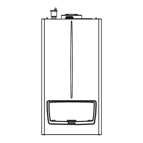
HaNDlING THE aPPlIaNcE aTTENTIoN: the casing sides are not load-bearing, so in order to move the appliance, it is necessary to take it from the rear and front as shown in the fig. 2 and not from the side. Fig. 2 DaTa NamEPlaTE PosITIoN Key (Fig. -
Page 11: Main Dimensions
maIN DImENsIoNs Key (Fig. 4): - Air intake - Electrical connection - Gas supply - System return - System flow - Condensate drain (minimum internal diameter Ø 13 mm) Fig. 4 Depth Height Width model (mm) (mm) (mm) 90 and 115 1098 (1233) Connections... -
Page 12: Minimum Installation Distances
mINImUm INsTallaTIoN DIsTaNcEs Key (Fig. 5): - 450 mm - 350 mm - 200 mm - 200 mm - 1000 mm Fig. 5 PosITIoN of THE aPPlIaNcEs The installation of appliances powered with gas with a greater density than 0.8 (l.P.G.) is only allowed in places above ground level, also communicating with places that are on the ground. -
Page 13: Antifreeze Protection
- The materials used for the central heating circuit of Alpha appliances resist propylene glycol based antifreeze liquids (if the mixtures are prepared perfectly). -
Page 14: Other Antifreeze Functions (Optionals)
oTHEr aNTIfrEEzE fUNcTIoNs (oPTIoNals) Depending on the system implemented and thus on the optional kits fitted, other Antifreeze functions may be available. External probe (optional) If the external probe is present, the appliance's pump or other pumps if installed (pump, Zone 1 pump, Zone 2 pump, System pump), is activated when the external temperature measured by the probe drops below the temperature set in the parameter "System settings/ Additional antifreeze protections/Outside temperature pump activation"... -
Page 15: Hydraulic Connection
1.11 HyDraUlIc coNNEcTIoN In order not to void the condensation module warranty, before making the device connections, carefully clean the heating system (pipes, radiators, etc.). A treatment of the heating and water system water is required, in compliance with the technical standards in force, in order to protect the system and the appliance from deposits (e.g. -
Page 16: Electrical Connection
During the chimney sweep function, the boiler flow temperature is limited by the parameters “Zone 1 CH setpoint” and “Zone 2 CH setpoint” and the parameter “CH setpoint hysteresis”. When using the 'System side flow sensor', the boiler flow temperature is limited by the maximum permissible temperature (95°C). If the system-side flow sensor is used, Boiler supply temperature is limited by the maximum permissible temperature (95°C). - Page 17 1. Press on the two hooks (b) at the top of the front control panel cover (a); 2. When releasing the front control panel lid (a), accompany its rotation until it is fully open, in order to access the P.C.B. (c) and display board (d).
- Page 18 If the power supply cable is damaged, it must be replaced by a special cable or assembly, which are only available from the manufacturer or its authorised after-sales Technical assistance centre. The power supply cable must be laid as shown (Fig. 9). If the fuses on the circuit boards need to be replaced, this must also be done by qualified personnel.
-
Page 19: Commands For Heat Adjustment (Optional)
1.13 commaNDs for HEaT aDjUsTmENT (oPTIoNal) The device is prepared for the application of the cascade and zone regulator, the zone manager, the remote control for single high-power boilers, on/off thermostats, commercial Opentherm modulators and the external probe. These components are available as separate kits to the boiler and are supplied on request. Carefully read the user and assembly instructions contained in the accessory kit. - Page 20 • constant setpoint The CH demand is generated permanently on both heating zones (it is not mandatory to configure both pumps of the two zones) (see also climate curve). Inputs OT1 and OT2 (in this case), can be used as setpoint reduction (open contact). With closed contact, the setpoint used is given by the parameters "Zone 1 CH setpoint"...
- Page 21 CH and DHW demand type parameter). If the BMS must be integrated into an existing home automation system or other than the Alpha system manager, the Authorised Technical Assistance Centre must be contacted for the configuration of the correct parameters.
- Page 22 By setting the parameter "CH Request type" within "HYDRAULIC SETTINGS" it is possible to configure the input by choosing the operating mode between "0-10 V Temperature control" and "0-10 V Power control" . By setting this parameter, both in temperature and in Power, the CH demand is subject to priority in DHW, deactivation CH Demand, Decreasing slope (function) and Minimum time.
- Page 23 • oTc climate curve - cH1 (zone 1 cH) TM (°C) TE (°C) Fig. 11 The graph in Fig. 11 is made by comparing the minimum central heating outdoor temperature value (+18 °C) with the minimum Zone 1 heating setpoint value (+20 °C) and the maximum central heating outdoor temperature value (-10 °C) with the maximum Zone 1 heating setpoint (+85 °C).
-
Page 24: Hydraulic Settings
1.14 HyDraUlIc sETTINGs system sensor Two heating zones (one of which can be mixed) and a DHW storage tank can be managed. relay settings See also Relay settings in chapter Maintenance. Using the configurable relays, the hydraulic diagrams shown on the following pages can be realised. These relays can be used to activate zone pumps, system pump, DHW pump, 3-way DHW valve, mixing valve, fault signal and Burner on. -
Page 25: Notes And Tables In Common Of Wiring Diagrams
1.15 NoTEs aND TablEs IN commoN of WIrING DIaGrams The notes and tables below apply to all diagrams in Fig. 14, 15, 16, 17, 18, 19, 20, 21, 22, 24, 25, 26, 27, 28, 29, 30, 31. For low-temperature zones, insert a safety thermostat in series with the relevant zone pump. Remove the X40 link wire in case of connection: * cascade and zone regulator * 0-10V... -
Page 26: Hydraulic Diagram - One Direct Zone - One Mixed Zone - Dhw Pump
1.16 HyDraUlIc DIaGram - oNE DIrEcT zoNE - oNE mIXED zoNE - DHW PUmP Fig. 13 Key (Fig. 13): - Minimum pressure switch with manual reset - Safety thermostat - Generator - Storage tank unit feeding pump - External probe - Non return valve - Manifold/mixer - External storage tank unit... -
Page 27: Wiring Diagram - One Direct Zone - One Mixed Zone - Dhw Pump
1.17 WIrING DIaGram - oNE DIrEcT zoNE - oNE mIXED zoNE - DHW PUmP Further notes on this diagram can be found in Para. 1.15. As a hydraulic diagram, please refer to Fig. 14. TA/2 TA/1 Link Fig. 14 Key (Fig. 24): Parameter configuration table A37 - Connection sheet (loads) "HyDraUlIc sETTINGs"... -
Page 28: Wiring Diagram - Two Direct Heating Zones - Dhw Pump - Open Therm Thermostat
1.18 WIrING DIaGram - TWo DIrEcT HEaTING zoNEs - DHW PUmP - oPENTHErm THErmosTaTs Further notes on this diagram can be found in Para. 1.15. As a hydraulic diagram, please refer to Fig. 15. Fig. 15 Key (Fig. 26): Parameter configuration table A37 - Connection sheet (loads) "HyDraUlIc sETTINGs"... -
Page 29: Wiring Diagram With High Power Remote Control
1.19 WIrING DIaGram WITH HIGH PoWEr rEmoTE coNTrol Key (Fig. 16): A25 - CLIP-IN (optional) A38 - Connection card (signals) - Room thermostat (optional) - Cable type: J-Y(St)Y 2x2x0,6. Maximum permitted length: 50 m - Address 0 Fig. 16 Remove link wire X40 The parameter "CH Request type"... -
Page 30: Wiring Diagram Bus-Cascade Connection
1.20 WIrING DIaGram bUs-cascaDE coNNEcTIoN ≤ 2 m ≤ 2 m... -
Page 31: Alpha Flue Systems
1.21 alPHa flUE sysTEms Alpha supplies various solutions separately from the appliances regarding the installation of air intake terminals and flue extraction, which are fundamental for appliance operation. Type c configuration, sealed chamber and fan assisted Extension pipes and concentric elbows push-fittings. -
Page 32: Equivalent Lengths Of Flue System Components
1.22 EqUIvalENT lENGTHs of alPHa flUE sysTEm comPoNENTs Equivalent length TyPE of DUcT to 1 m of pipe concentric Ø 110/160 Concentric pipe Ø 110/160 1m m 1,0 Ø 110/160 45° concentric bend m 1,0 Concentric bend 90° Ø 110/160 m 1,7 Terminal complete with concentric horizontal intake-exhaust Ø... -
Page 33: Cap Removal For Concentric Kit Installation
1.23 caP rEmoval for coNcENTrIc KIT INsTallaTIoN In order to be able to install the concentric kits, it is necessary to remove the factory fitted cap on the concentric intake. Key (Fig. 18): - Screw - Concentric intake cap Fig. 18 1.24 coNcENTrIc HorIzoNTal KIT INsTallaTIoN Type c configuration, sealed chamber and fan assisted The position of the terminal (in terms of distances from openings, overlooking buildings, decking, etc.) must be set up in compliance... - Page 34 Horizontal intake - exhaust assembly kit Ø 110/160 (fig. 19) 1. Remove the Ø 160 cap on the concentric intake, with its gasket (Fig. 19) by unscrewing the fixing screw. 2. Engage the bend (1) with the male (smooth) side up to the end stop of the flue flange of the appliance; 3.
- Page 35 Extension pipes and concentric elbows push-fittings. To install push-fitting extensions with other elements of the flue, proceed as follows: - Install the concentric pipe or elbow with the male side (smooth) on the female side (with lip seal) to the end stop on the previously installed element in order to ensure sealing efficiency of the coupling.
-
Page 36: Concentric Vertical Kit Installation
1.25 coNcENTrIc vErTIcal KIT INsTallaTIoN Type c configuration, sealed chamber and fan assisted Concentric vertical intake and exhaust kit. This vertical terminal is connected directly to the outside of the building for air intake and flue gas exhaust. The vertical kit with aluminium tile enables installation on terraces and roofs with a maximum slope of 45% (approx 25°) and the height between the terminal cap and half-shell (260 mm) must always be respected. -
Page 37: Intake Stub Pipe Kit Installation For Type B Configurations
1.26 INTaKE sTUb PIPE KIT INsTallaTIoN for TyPE b coNfIGUraTIoNs Installation of the intake stub pipe kit (fig. 24) Unscrew the screws (1) securing the Ø 100 intake cap; 1. Remove the factory-assembled suction cap (2); 2. Place the gasket (5) of the stub pipe kit on the newly freed intake hole; 3. -
Page 38: Installation Of Ø 100 Horizontal Terminals
1.27 INsTallaTIoN of 100 Ø HorIzoNTal TErmINals configuration type b, open chamber and fan assisted Installation of horizontal kit Ø100 with wall flue exhaust (fig. 25) 1. Install the reduction Ø 110-Ø 100 (1) on the boiler exhaust up to the end stop. 2. -
Page 39: Separator Kit Installation
1.28 sEParaTor KIT INsTallaTIoN Type c configuration, sealed chamber and fan assisted separator kit Ø 100/100 This kit allows air to come in from outside the building and the exhaust to exit from the chimney, flue or intubated duct through divided flue exhaust and air intake pipes. - Page 40 Extensions for separator kit (l = maximum length) The maximum straight length (without bends) that can be used vertically for Ø 100 intake and exhaust pipes is 25m for Pro Tec 90NX, 20m for Pro Tec 115NX and 15m for Pro Tec 150NX, understood as the sum of intake and exhaust.
-
Page 41: Maximum Flue Length
1.29 maXImUm flUE lENGTH Pro Tec 90NX Type Installation Pro Tec 90NX L = Maximum length (m) 110/160mm C13 (horizontal+curve) C33 (vertical) C43 - C53 - C83 (split) 100/100mm B23 - B23p - B33 - B53 - B53p a = maximum flue length with both mushroom and thermoformed flue. If the clapet valve is inserted into the outlet, the maximum length is reduced from 20 to 10 metres. -
Page 42: Configuration For C6 Flue Installations
1.30 coNfIGUraTIoN for c6 flUE INsTallaTIoN Pro Tec 90NX Gas type Flue temperature at maximum output °C Flue gas mass at maximum power kg/h Flue temperature at minimum output °C Flue gas mass at minimum power kg/h at Q. max. -
Page 43: Water Treatment Plant Filling
1.31 WaTEr TrEaTmENT PlaNT fIllING As already mentioned in the previous paragraphs, a treatment of the thermal and domestic system water (when paired with a storage tank unit) is required, in compliance with the local standards in force. The parameters that influence the duration and proper operation of the heat exchanger are the water's PH, total hardness, conductivity, and oxygen, together with the system's processing residues (any welding residues), any oil present and corrosion products that can, in turn, cause damage to the heat exchanger. -
Page 44: Operation With System Flow Sensor
1.34 oPEraTIoN WITH sysTEm floW sENsor In the presence of a hydraulic separator, a System sensor must be provided. The system sensor is connected to terminals S1 and S2 and must be configured via the parameter "System sensor" (Technician menu/ HYDRAULIC SETTINGS). -
Page 45: Simple Cascade
1.35 sImPlE cascaDE By connecting two or more boilers electrically via BUS, a simple cascade can be configured. Make the BUS connection as shown in the diagram (Fig. 17). A system flow sensor is required in this configuration, see relevant example installation wiring diagrams in the cascade booklet. If the system flow sensor fails, the system will still function but with reduced performance. -
Page 46: Autodetection
1.36 aUToDETEcTIoN This function makes it possible to detect and associate appliances in cascade in the case of simple cascade installation. It also serves to assign the role of Master and Slave to devices in simple cascade or, to revert to a single configuration from simple cascade. Ensure that the communication BUS for simple cascade has been connected as in the diagram in Fig. -
Page 47: Heating Zones
1.38 HEaTING zoNEs Using the appliance's P.C.B., two separate zones can be managed in CH mode, and one of these can be mixed. The system flow probe is required and, in the case of the mixed zone, the low temperature flow probe is also required. When using the system-side flow sensor and hydraulic separator, the flow temperature of the unit (or units in the case of simple cascade) is limited by the maximum permissible temperature (95°C). -
Page 48: Anti-Legionella
1.41 aNTI-lEGIoNElla The menu "Antilegionella" is present if the parameter "DHW request type" is set as "Sensor". The function must be enabled by the 'Function' parameter and the temperature read by the DHW probe must be lower than the setpoint parameter (anti-legionella) to be activated. -
Page 49: Appliance Start-Up (Ignition)
1.44 aPPlIaNcE sTarT-UP (IGNITIoN) To commission the appliance (the operations listed below must only be performed by qualified personnel and in the presence of staff only): 1. Check that the internal system is properly sealed according to the specifications set forth by regulations in force. 2. - Page 50 Pump lED Pro Tec 90, 115NX - LED off: circulator not powered - Fixed green LED: circulator powered or running - Flashing red LED (temporary error): pump is making attempts to unblock; overload; pump driven by external flow; overtemperature; overvoltage; undervoltage - Fixed red LED (permanent error): pump blocked (unblock the rotor mechanically - de-energise for approx.
- Page 51 Pro Tec 90NX 500 1000 1500 2000 2500 3000 3500 4000 4500 5000 5500 Fig. 31 Pro Tec 115NX 500 1000 1500 2000 2500 3000 3500 4000 4500 5000 5500 6000 Fig. 32 Key (Fig. 31,32) Area between curves 1 and 2 = Available system head...
-
Page 52: Kits Available On Request
A wide range of accessories are available for the Pro Tec NX range to meet all different installation needs. Check the complete list of kits available and which can be combined with the product, contact Alpha Technical support for further details. -
Page 53: Main Components
1.47 maIN comPoNENTs Pro Tec 90, 115NX Fig. 34 Key (Fig. 34): - Concentric intake cap Ø 160 - Sample points (air A) - (flue gases F) - Gas cock - Flange connection module-flue hood - Draining funnel - Igniter - Safety valve 5.5 bar - Combustion group - Condensate siphon... - Page 54 Pro Tec 150NX Fig. 35 Key (Fig. 35): - Concentric intake cap Ø 160 - Sample points (air A) - (flue gases F) - Draining funnel - Flue probe with thermofuse - Gas cock - Igniter - Safety valve 5.5 bar - Combustion group - Condensate siphon - Ignition glow plug...
-
Page 55: Instructions For Use And Maintenance
INsTrUcTIoNs for UsE aND maINTENaNcE GENEral rEcommENDaTIoNs Never expose the wall-mounted appliance to direct vapours from a hob. for safety purposes, check that the air intake/flue exhaust terminals (if fitted) are not blocked. If temporary shutdown of the appliance is required, proceed as follows: a) drain the heating system if antifreeze is not used;... -
Page 56: Cleaning And Maintenance
The use of components involving use of electrical power requires some fundamental rules to be observed such as: do not touch the appliance with wet or moist parts of the body; do not touch when barefoot; never pull electrical cables or leave the appliance exposed to atmospheric agents (rain, sunlight, etc.); the appliance power cable must not be replaced by the user;... -
Page 57: Control Panel
2.3 coNTrol PaNEl Fig. 36 Key (Fig. 36): - Indicates the central heating setpoint temperature - Main switch - Central heating mode enabled - Multifunction display (main screen) - Indicates burner on and relative output scale - Sliding door - Hourly heating programming active mode (ON, OFF, ECO) of - Function keys central heating schedule - Instrument pressure gauge... -
Page 58: Using The Appliance
UsING THE aPPlIaNcE Before ignition, make sure that the system is full of water, checking that the pressure gauge (Fig. 68) indicates a base value at which the system has been designed and calculated and however not less than 0.5 bar. –... - Page 59 CENTRAL HEATING Outside temperature Zone 1 CH setpoint Outside temperature for CH off 85°C Zone 2 CH setpoint Zone 1 Offset 35°C 0°C Outside temperature Zone 2 Offset 0°C Zone 1 CH ECO setpoint reduction 30°C Zone 2 CH ECO setpoint reduction 5°C To select To confirm...
-
Page 60: Weekly Schedule
2.5 WEEKly scHEDUlE Time programming allows you to define the operating times of the device. Two independent programmes are available, one for CH and one for DHW. To activate programming, you must enter the menus CENTRAL HEATING" and DOMESTIC HOT WATER" and under the parameter "Enable/disable scheduler"... -
Page 61: Holidays
- Zone 1 CH ECO setpoint reduction; - Zone 2 CH ECO setpoint reduction; - ECO shutdown hysteresis CH Zone 1; - ECO shutdown hysteresis CH Zone 2. The parameter for the function "ECO" in DHW is as follows: - ECO setpoint reduction. If parameters "ECO shutdown hysteresis CH Zone 1"... -
Page 62: User Menu
2.8 UsEr mENU Press the “MENU” button to access a list of variables that enable you to customise use of the system. Hereunder is a list of available menus: mENU menu item Description USER Allows selection of the user menu TECHNICIAN Allows selection of the technical menu (access allowed via password for Service only) UsEr mENU... - Page 63 restore customised menu item Description range Default settings value Sets the temperature that will be subtracted from the actual setpoint for heating zone 1 when the "ECO" mode is activated. Zone 1 CH ECO setpoint If the parameter "CH Request type "Valve 0 ÷...
- Page 64 UsEr mENU/cENTral HEaTING/oUTDoor TEmPEraTUrE restore customised menu item Description range Default settings value Defines the outside temperature at which Outside temperature for CH 7 ÷ 25 OTC will disable central heating (even if the (°C) room thermostat demand is active). This is the offset value to be added on zone 1 to Zone 1 Offset -15 ÷...
- Page 65 When Thermostat is set in Technician menu/HYDRAULIC SETTINGS/DHW request type, the table below will look like this: UsEr mENU/HolIDay/HolIDay moDE restore customised menu item Description range Default settings value Sets the zone 1 heating setpoint when Zone 1 "Holiday mode" is active minimum If the parameter "Zone 1 CH setpoint"...
- Page 66 When Sensor is set in Technician menu/HYDRAULIC SETTINGS/DHW request type, the table below will look like this: UsEr mENU/HolIDay/HolIDay moDE restore customised menu item Description range Default settings value Sets the zone 1 heating setpoint when Zone 1 "Holiday mode" is active. minimum If the parameter "Zone 1 CH setpoint"...
- Page 67 UsEr mENU/sETTINGs/UsEr INTErfacE restore customised menu item Description range Default settings value English Italian Bulgarian Czech Greek French Flemish Polish Portuguese Select language * Allows the selection of the desired language. English Slovak Spanish Romanian Russian Slovenian German Turkish Ukrainian Hungarian Imperial Allows selection of the unit of measurement...
- Page 68 UsEr mENU/DIaGNosTIcs/boIlEr sTaTE menu item Description CH - Primary circuit Displayed when the setpoint is reached and the burner is switched off during "CH Demand". setpoint reached CH Demand Displayed when "CH Demand" is active. CH/DHW Demand Displayed when parameter "Parallel mode" is active and "CH Demand" and "DHW Demand" are active at the same time. CH Postpump Displayed at the end of "CH Demand"...
- Page 69 UsEr mENU/DIaGNosTIcs/sysTEm INformaTIoN menu item Description Flame current* Value in µA. Actual fan speed Real-time fan speed (rpm). Requested fan speed Fan setpoint (rpm). Modulation level * Effective burner output value (%). Boiler setpoint* Temperature value calculated by the system (°C). CH setpoint Required temperature value during heating (°C).
- Page 70 UsEr mENU/DIaGNosTIcs/fIrmWarE rElEasE menu item Description Display Views the display board firmware version. Main board Displays the P.C.B. firmware version. UsEr mENU/maINTENaNcE menu item Description Service information Displays the telephone number of the service centre. Service due date Date of next maintenance (see error code 102).
-
Page 71: Fault And Anomaly Signals
faUlT aND aNomaly sIGNals The appliance signals any malfunction by means of a numerical code and description on the multifunction display. From this screen you can: - Reset the current error (if the error is resettable) by pressing the 'OK' button; - if the ESC key is pressed, the main screen appears and the error will appear at the top of the display in place of the date and time;... - Page 72 Error anomaly signalled cause appliance status / solution code The board detects a short-circuit on the system flow supply sensor shorted (2) (1) regulation NTC probe. The board detects an open contact on the system flow supply sensor open (2) (1) regulation NTC probe.
- Page 73 Error anomaly signalled cause appliance status / solution code The burner is switched off to prevent any damage to the condensing module, once the correct ΔT has been restored and the time of 1 minute has elapsed since the appearance of the The boiler detects a sudden, unexpected increase in the ΔT fault, the appliance returns to normal Delta T protection...
- Page 74 Error anomaly signalled cause appliance status / solution code The board detects a short-circuit on the system-side flow system sensor shorted NTC probe (no guarantee of efficient operation of the (2) (1) system). The board detects an open contact on the system-side flow system sensor open (2) (1) NTC probe (no guarantee of efficient system operation).
- Page 75 Authorised After-Sales Technical from the menu "TECHNICIAN". Assistance Centre). (1) If the shutdown or fault persists, contact contact alpha Technical. (2) If normal operating conditions are restored, the appliance re-starts without having to be reset.
-
Page 76: Appliance Switch-Off
2.10 aPPlIaNcE sWITcH-off Switch the appliance off by putting it in “off” mode, disconnect the main switch outside of the appliance and close the gas cock upstream of the appliance. Never leave the appliance switched on if left unused for prolonged periods. 2.11 rEsTorE cENTral HEaTING sysTEm PrEssUrE 1. -
Page 77: Antifreeze Protection
2.13 aNTIfrEEzE ProTEcTIoN The appliance has an antifreeze function that switches the burner on automatically when the temperature drops below 9°C (standard protection to minimum temperature of -5°C). In order to guarantee the integrity of the appliance and the domestic hot water heating system in areas where the temperature drops below zero, we recommend protecting the central heating system using anti-freeze liquid If there is a storage tank in the system and a DHW probe, the burner is switched on when the temperature measured by the probe falls below 6°C and is switched off above 15°C. -
Page 78: Instructions For Maintenance And Initial Check
These will also compromise the product’s compliance, and the said product may no longer be valid and fail to meet the current regulations. in regard to the above, only use original Alpha spare parts when replacing components. If additional documentation needs to be consulted for extraordinary maintenance, contact the Authorised After-Sales Service. -
Page 79: Initial Check
INITIal cHEcK commissioning the appliance requires you to: - Ensure that the type of gas used corresponds to the appliance settings (the type of gas appears on the display on first electrical power supply, on the data nameplate or, with the display already on, with the following sequence: MENU - Information - Ok); - Check connection to a 230V-50Hz power mains, correct L-N polarity and the earthing connection;... -
Page 80: Yearly Appliance Check And Maintenance
yEarly aPPlIaNcE cHEcK aND maINTENaNcE The following checks and maintenance should be performed once a year to ensure operation, safety and efficiency of the appliance over time. - Clean the flue side of the heat exchanger. - Clean the main burner. - Check the correct positioning, integrity and cleanliness of the detection and ignition electrode;... - Page 81 Pro Tec 90NX Gas type to nominal q. to minimum q. 9,3 (9,2 ÷ 9,6) 8,9 (8,6 ÷ 9,0) 10,3 (10,2 ÷ 10,6) 9,9 (9,7 ÷ 10,1) Gas type at Nominal q. at minimum q. 4,2 (4,4 ÷ 3,7) 5,0 (5,5 ÷ 4,8)
-
Page 82: Hydraulic Diagram
HyDraUlIc DIaGram 13 14 Fig. 43 Key (Fig. 43): - Heat-exchanger safety thermostat (manual reset) - Draining funnel on view - Flue probe with thermofuse - Device emptying cock - Burner - Safety valve 5.5 bar - Heat exchanger safety thermofuse - Flow manifold - Ignition electrode - Pressure transducer... -
Page 83: Wiring Diagram
WIrING DIaGrams Pro Tec 90, 115NX Fig. 44... - Page 84 Pro Tec 150NX Fig. 45...
- Page 85 Key (Figs. 44, 45): Key (Figs. 44, 45): - Circuit board - 230 Vac 50Hz Power supply - Display board - Testing/iXTool (Bus microm) - CLIP-IN (Optional - part No.1.037171) - External reset (Optional) - Cascade and zone regulator - Bus openTherm 1 - Connection sheet (loads) - Bus openTherm 2 - Connection card (signals)
- Page 86 maximum loads on relays of boards a2 and a4 Multifunction Voltage Current cosφ From factory relay settings, K70 Programmable relays do not relays perform any K70-A2/K70-A3 230 Vac < 0.1 A ≥ 0,6 functions. K70-A4/K70-A5 K70-A1 Insert an optional Potential-free external relay to Run/fault signal contact (230 Vac...
-
Page 87: Troubleshooting
TroUblEsHooTING Trouble Possible causes solutions Caused by leakage from gas circuit smell of gas Check sealing efficiency of gas intake circuit. pipelines. Check the presence of pressure in the network and that the gas adduction repeated ignition blocks No gas. cock is open. -
Page 88: Technical Menu
TEcHNIcal mENU Press the “MENU” button to access a list of variables that enable you to customise use of the system. Hereunder is a list of available menus: mENU menu item Description USER Allows selection of the user menu TECHNICIAN Allows selection of the technical menu (access allowed via password for Service only) To access the technical menu, enter the password '123' using the '+' and '-' buttons, pressing 'OK' with each entered digit. - Page 89 TEcHNIcIaN mENU/HyDraUlIc sETTINGs/rElay sETTINGs restore value menu item Description range Default settings customized K70-A1 Relay not used Booster pump K70-A2 Zone 1 pump K70-A3 Zone 2 pump K70-A4 System pump DHW pump System fault 3-way valve CH Each relay has a dedicated K70-A5 3-way valve DHW parameter to determine its...
- Page 90 TEcHNIcIaN mENU/HyDraUlIc sETTINGs/mIX zoNE restore value menu item Description range Default settings customized Selects the mixed heating zone (mixing valve, Mix zone selection* sensor). Only one heating zone can be 1 ÷ 2 equipped with a mixing valve. Running time of the mixing valve. 1 ÷...
- Page 91 TEcHNIcIaN mENU/HyDraUlIc sETTINGs/cH rEqUEsT TyPE restore value menu item Description range Default settings customized Room thermostat OTC They allow the selection of Room thermostat OTC Room thermostat setpoint different demands Room thermostat setpoint Room Only OTC according to the type of Only OTC thermostat installation:...
- Page 92 TEcHNIcIaN mENU/HyDraUlIc sETTINGs/3-Way valvE restore value menu item Description range Default settings customized 3-way valve selection: Motorized Motorised (Motorised diverter valve) ÷ 3-way valve selection Spring return (Diverter valve with spring Motorized Spring return) return See diagram in Para. 1.16. Defines the time during which the 'electric' valve is energised to switch the position from 1 ÷...
- Page 93 TEcHNIcIaN mENU/cH sETTINGs/TEmPEraTUrEs restore customised menu item Description range Default settings value Zone 1 maximum CH 15 ÷ 90 Set the "Zone 1 maximum CH setpoint. setpoint (°C) (°C) ÷ Zone 1 minimum CH Zone 1 Set the "Zone 1 minimum CH setpoint". setpoint maximum (°C)
- Page 94 TEcHNIcIaN mENU/cH sETTINGs/TEmPEraTUrEs restore customised menu item Description range Default settings value Sets the temperature that will be subtracted from the actual setpoint for heating zone 1 when the "ECO" mode is activated. Zone 1 CH ECO setpoint If the parameter "CH Request typeValve time 0 ÷...
- Page 95 TEcHNIcIaN mENU/cH sETTINGs/TEmPEraTUrEs restore customised menu item Description range Default settings value If set other than 0 and when the "ECO" mode is active, the CH demand is inhibited when the calculated setpoint is lower than the temperature set on the Zone 2 setpoint parameter.
- Page 96 TEcHNIcIaN mENU/cH sETTINGs/ovErTEmPEraTUrE restore customised menu item Description range Default settings value Each time the burner is switched on and 0 ÷ 10 Overtemperature timer* during the time set by the parameter (min) (min) "Overtemperature timer", the burner is switched off at a temperature value increased Overtemperature hysteresis 0 ÷...
- Page 97 TEcHNIcIaN mENU/cH sETTINGs/TImING sETTING restore customised menu item Description range Default settings value 0 ÷ -20 Post pump time [min] Set the heating pump delay time (min) (min) Set the anti-cycle timer (minimum time 0 ÷ 15 Anticycling timer between boiler switch-off and next switch on) (min) (min) The boiler output is adjusted so that the...
- Page 98 When Thermostat is set in Technician menu/HYDRAULIC SETTINGS/DHW request type, the table below will look like this: TEcHNIcIaN mENU/DomEsTIc HoT WaTEr/TEmPEraTUrEs restore customised menu item Description range Default settings value Storage temperature Sets the flow temperature during the 35 ÷ 87 setpoint "Domestic hot water"...
- Page 99 TEcHNIcIaN mENU/DomEsTIc HoT WaTEr/TImING sETTING restore customised menu item Description range Default settings value 0 ÷ 59 Post pump time [sec] Set the "DHW Postpump" time in seconds. Set the time for "DHW Postpump" in 0 ÷ 30 Post pump time [min] minutes.
- Page 100 Fan parameters Pump parameters Delta T parameters Boiler antifreeze protection Additional antifreeze protections Decreasing slope User interface settings Anti-humidity settings Modbus parameters 10. Maintenance Pro Tec 90NX TEcHNIcIaN mENU/sysTEm sETTINGs/faN ParamETErs Default restore customised menu item Description range appliance settings...
- Page 101 Pro Tec 115NX TEcHNIcIaN mENU/sysTEm sETTINGs/faN ParamETErs restore customised menu item Description range Default settings value See table 750-6750 Para. "4.2 Ignition speed * Sets the speed used during burner ignition. (rpm) Combustion parameters". This defines the max fan speed and therefore Minimum See table the maximum relative operating power of the...
- Page 102 victrix Pro v2 150 EU TEcHNIcIaN mENU/sysTEm sETTINGs/faN ParamETErs Default restore customised menu item Description range appliance settings value See table 750-6750 Para. "4.2 Ignition speed * Sets the speed used during burner ignition. (rpm) Combustion parameters". This defines the max fan speed and therefore Minimum See table the maximum relative operating power of the...
- Page 103 TEcHNIcIaN mENU/sysTEm sETTINGs/PUmP ParamETErs Default restore value menu item Description range appliance settings customized Disabled Disabled = pump feedback is not used Feedback ÷ Enabled Enabled = pump feedback is used Enabled PWM = the pump feedback signal is a PWM based signal (only for Feedback signal type...
- Page 104 TEcHNIcIaN mENU/sysTEm sETTINGs/aDDITIoNal aNTIfrEEzE ProTEcTIoNs restore customised menu item Description range Default settings value Defines the antifreeze activation threshold. Antifreeze activation This threshold is monitored by the (system) 2 ÷ 20 temperature sensor (if present) in order to protect the (°C) (°C) system.
- Page 105 TEcHNIcIaN mENU/sysTEm sETTINGs/moDbUs ParamETErs restore customised menu item Description range Default settings value Allows the assignment of the Modbus slave Address 1 ÷ 247 address (when used with BMS systems). 1200 2400 4800 Baudrate Modbus transmission rate. 9600 9600 19200 38400 The first digit (8 fixed value) defines the number of bits per byte.
- Page 106 TEcHNIcIaN mENU/maNUal TEsT menu item Description Activates "Function" "Chimney sweep" for single boiler or for one or more boilers if simple Chimney sweep cascade installation (for more details, see Para. 3.11). Check the "Function" associated with the relay previously set in "Technician menu/ HYDRAULIC SETTINGS/Relay settings".
-
Page 107: Programming
TEcHNIcIaN mENU/cascaDE Settings Single burner power Autodetect Parameter synchronization The parameter ' A utodetect' is also used by the individual device (Para. 1.33). Although the remaining parameters are also present on the individual boiler, they can be set when the appliance is part of a cascade installation. For setting and explanation of parameters, please refer to the cascade booklet. -
Page 108: Converting The Appliance To Other Types Of Gas
coNvErTING THE aPPlIaNcE To oTHEr TyPEs of Gas The gas conversion operation must be carried out by an authorised company (e.g. Authorised Technical Assistance Service). The pressure testers used for calibration should be perfectly closed and there should be no leaks from the gas circuit. - Page 109 Pro Tec 90, 115NX sIT 822 Gas valve Key (Fig. 46): - Wiring connector - Outlet gas flow rate adjuster - Pressure regulator connection (PR) - Gas valve outlet pressure point - Gas valve inlet pressure point Fig. 46 Pro Tec 150NX Honeywell Gas valve (rambler vK4405v) Key (Fig.
-
Page 110: Co Regulation
3.10 co rEGUlaTIoN To have an exact value of CO in the flue, the technician must insert the sampling probe to the bottom of the sample point. The verification operations of the CO must be carried out with the casing mounted, while the gas valve calibration operations must be carried out with the casing open and removing the voltage from the appliance. -
Page 111: Chimney Sweep
3.11 cHImNEy sWEEP This function, which can be activated at Technician menu/Manual test, allows the technician to check combustion parameters. The operating temperature is limited by the parameters "Zone 1 CH setpoint" and "Zone 2 CH setpoint". If the system-side flow sensor is used, the above two parameters limit the temperature on the hydraulic circuit where the system-side flow sensor is installed. -
Page 112: Antifreeze
3.15 aNTIfrEEzE The antifreeze is also active when the appliance is in standby mode or when CH and/or DHW is disabled. radiators The appliance is equipped with a function that starts the burner if the system flow water is below 9°C. The burner is switched off when the system flow water reaches approximately 35°C. -
Page 113: Assembling The Manifold On The Condensation Module
3.17 assEmblING THE maNIfolD oN THE coNDENsaTIoN moDUlE The maximum tightening force in assembling the manifold (2) on the condensation module (3) must be 5 Nm. assembling the manifold on the condensation module (fig. 51) 1. Set the manifold (2) on the module. 2. -
Page 114: Replacing The Manifold Insulation Panel
3.18 rEPlacING THE maNIfolD INsUlaTING PaNEl 1. Unscrew the fixing screws (6) of the ignition and detection electrodes (5) and remove them. 2. Remove the insulating panel (1) by actuating a blade (2) under its surface. 3. Remove the residue of the fixing adhesive from the surface of the manifold (3). 4. -
Page 115: Casing Removal
3.19 casING rEmoval To facilitate appliance maintenance the casing can be completely removed as follows: front panel (fig.54) 1. Loosen the two screws (a). 2. Pull the front casing (b) towards you. 3. Push the front casing upwards, releasing it from the upper pins (c). 4. - Page 116 sides (fig. 55) 5. Tilt the control panel (e) towards you. 6. Unscrew the four screws (f) in order to remove the lower grid (g). 7. Unscrew the four screws (h). 8. Remove the side panels (i) by opening them slightly outwards and then lifting them first upwards and then pulling them towards you, so that they disengage from the rear seats (Ref.
- Page 117 sealed chamber cover (fig. 56) 9. Unscrew the eight screws (l). 10. Swing the airtight chamber cover (m) towards yourself so that it can be removed from the two rebated screws at the top of the frame and released. Fig. 56...
-
Page 118: Technical Data
The power data in the table has been obtained with intake-exhaust pipe measuring 0.5 m in length. Gas flow rates refer to net calorific value below a temperature of 15°C and at a pressure of 1013 mbar. Pro Tec 90NX mETHaNE... - Page 119 Pro Tec 150NX mETHaNE ProPaNE (G20) (G31) Gas floW floW raTE HEaT Gas floW raTE faN rEvs moDUlaTIoN raTE faN rEvs moDUlaTIoN oUTPUT oUTPUT bUrNEr bUrNEr (kW) (kW) (rpm) (rpm) (kg/h) 141,0 138,3 7400 14,92 6950 10,95 134,0 131,4 7050 14,18 6625 10,41...
-
Page 120: Combustion Parameters
20% (referring to the gas distributed in the network), all calibration operations of the device must refer to the O values of the gas G20 given in the following tables. Pro Tec 90NX Gas type Supply pressure... - Page 121 Pro Tec 150NX Gas type Supply pressure mbar Gas nozzle diameter 11,7 Ignition fan speed 2200 2600 Post ventilation fan speed 4000 4000 Flue flow rate at heating nominal heat output kg/h Flue flow rate at min heat output kg/h at Nominal Q.
-
Page 122: Technical Data Table
4.3 TEcHNIcal DaTa TablE Pro Tec 90NX Pro Tec 115NX Pro Tec 150NX Central heating nominal heat input 93,0 114,5 141,0 Minimum heat input 10,1 11,7 29,0 PoCentral heating nominal heat input with 20%H2NG 88,7 109,0 131,3 Minimum heat input with 20%H2NG gas... -
Page 123: Data Plate
DaTa PlaTE Cod.Md. Sr N° Type Qnw/Qn min Qnw/Qn max Pn min Pn max NOx Class CONDENSING Fig. 57 The technical data are provided on the data plate on the appliance. Model Cod. Md. Model code Sr N° Serial Number Check PIN code Minimum and maximum installation temperature... -
Page 124: Technical Parameters For Combination Boilers (In Compliance With Regulation 813/2013)
4.5 TEcHNIcal ParamETErs for combINaTIoN boIlErs (IN comPlIaNcE WITH rEGUlaTIoN 813/2013) The efficiencies and NO values in the following tables refer to the gross calorific value. model Pro Tec 90NX Condensing Boiler Low temperature boiler Boiler type B1 Co-generation appliance for central heating... - Page 125 model Pro Tec 115NX Condensing Boiler Low temperature boiler Boiler type B1 Co-generation appliance for central heating Mixed heating appliance Nominal heat output Seasonal energy efficiency of central heating η For central heating only and combination boilers: useful heat output At nominal heat output in high temperature mode (*) 112,3 At 30% of nominal heat output in a low temperature mode (**)
-
Page 126: Product Fiche (In Compliance With Regulation 811/2013)
(**) Low temperature mode for condensation Boilers means 30°C , for low temperature boilers 37°C and for other appliances 50°C of return temperature. ProDUcT fIcHE (IN comPlIaNcE WITH rEGUlaTIoN 811/2013) Pro Tec 90NX Parameter value Annual energy consumption for the central heating mode (QHE) Seasonal space heating energy efficiency (ηs) -
Page 127: Parameters For Filling In The Package Fiche
ParamETErs for fIllING IN THE PacKaGE fIcHE If an assembly is to be made from this device, use the assembly sheets shown in (Fig. 61 and 62). For the correct compilation, insert into the appropriate spaces (as shown in the facsimile package fiche (Fig. 59 and 61) the values set out in the tables "Parameters for compiling package fiche"... - Page 128 facsimile for filling in the domestic hot water production system package fiche ‘I’ Solar contribution From the board of the solar device Auxiliary electricity ( 1.1 x ‘I’ 10 % ) ‘II’ ‘III’ - ‘I’ average climate conditions < 27 % ≥...
- Page 129 Parameters for filling in the DHW package fiche Parameter Pro Tec 90NX Pro Tec 115NX Pro Tec 150NX "I" "II" "III" * to be determined according to Regulation 811/2013 and transient calculation methods as per Notice of the European Community no.
- Page 130 Parameters for filling in the assembly chart Parameter Pro Tec 90NX Pro Tec 115NX Pro Tec 150NX "I" "II" "III" 0,29 0,24 0,19 "IV" 0,12 0,09 0,08 * to be established by means of table 5 of Regulation 811/2013 in case of “assembly” including a heat pump to integrate the boiler. In this case the boiler must be considered as the main appliance of the assembly.
- Page 131 GAS BOILER SYSTEM COMMISSIONING CHECKLIST & WARRANTY VALIDATION RECORD Address: Boiler make and model: Boiler serial number: Commissioned by (PRINT NAME): Gas Safe registration number: Company name: Telephone number: Company email: Company address: Commissioning date: Heating and hot water system complies with the appropriate Building Regulations? Optional: Building Regulations Notification Number (if applicable): Time, temperature control and boiler interlock provided for central heating and hot water Boiler Plus requirements (tick the appropriate box(s))
- Page 132 SERVICE & INTERIM BOILER WORK RECORD It is recommended that your boiler and heating system are regularly serviced and maintained, in line with manufacturers’ instructions, and that the appropriate service / interim work record is completed. Service provider When completing a service record (as below), please ensure you have carried out the service as described in the manufacturers’ instructions. Always use the manufacturers’...
- Page 133 SERVICE & INTERIM BOILER WORK RECORD It is recommended that your boiler and heating system are regularly serviced and maintained, in line with manufacturers’ instructions, and that the appropriate service / interim work record is completed. Service provider When completing a service record (as below), please ensure you have carried out the service as described in the manufacturers’ instructions. Always use the manufacturers’...
- Page 134 SERVICE & INTERIM BOILER WORK RECORD It is recommended that your boiler and heating system are regularly serviced and maintained, in line with manufacturers’ instructions, and that the appropriate service / interim work record is completed. Service provider When completing a service record (as below), please ensure you have carried out the service as described in the manufacturers’ instructions. Always use the manufacturers specified spare parts.
- Page 136 These instructions have been carefully prepared but we reserve the right to Sevenoaks, Kent TN15 7RS alter the specification at any time in the interest of product improvement. © Alpha Therm Limited 2023. Tel: 0344 8718764 email: info@alpha-innovation.co.uk Part No. 1.04???? rev. ST.00????/000 website:www.alpha-innovation.co.uk...
Need help?
Do you have a question about the Pro Tec 90NX and is the answer not in the manual?
Questions and answers