Table of Contents
Advertisement
Quick Links
Advertisement
Table of Contents

Subscribe to Our Youtube Channel
Related Manuals for Toptica CoSy

Summary of Contents for Toptica CoSy
- Page 1 CoSy User Manual...
- Page 2 TEM Messtechnik GmbH Lochhamer Schlag 19 Grosser Hillen 38 D-82166 Graefelfing D-30559 Hannover Germany Germany Tel.: 089-85837-0 Tel.: 0511-510896-31 Fax: 089-85837-200 Fax: 0511-510896-38 E-mail: sales@toptica.com E-mail: info@TEM-messtechnik.de URL: http://www.toptica.com URL: http://www.TEM-Messtechnik.de CoSy Manual TOP en230215.doc, Stand 16.02.2024 08:41:00 2 (27)
-
Page 3: Table Of Contents
Shipping materials ..................8 3.1.1 System preconditions ................8 Brief description of the control elements ............9 3.2.1 Control elements situated on the CoSy measurement head ....9 3.2.2 CoSyControl control elements............. 10 3.2.3 CoSyControl block diagram..............12 Mechanical setup and electrical connections ............ 13 Setup ...................... -
Page 4: Product Description
-absorption line Usually this is achieved by using a relatively complex opto-mechanical setup. The truly compact CoSy system contains this setup and also all the evaluation electronics needed to obtain a Doppler free saturation spectrum as an output voltage directly observable e.g. on an oscilloscope. The Laser irradiating the System can thus be stabilised to any of the detected lines. - Page 5 CoSy measurement head. Fig. 1.3 The CoSy measurement head from the inside For operation a free laser beam is directed into the Cosy measurement head where it is split several times in order to traverse the glass cell on different paths, falling onto three different photo diodes.
-
Page 6: Chemical Elements Available For Spectroscopy Cell
CoSy User Manual 1.2 Chemical elements available for spectroscopy cell The standard version of CoSy is delivered with the glass cell containing the following alkali metals: • „Cs“: Caesium ( • „Rb“: Rubidium (mixture of Rb and • “K”: Potassium ( (other elements available on request). -
Page 7: Safety Instructions
CoSy User Manual Safety instructions Please read this manual carefully before operating any part of your CoSy system to avoid any damage to objects or persons Warning! The CoSy system is being used in Laser systems with partially invisible laser radiation. -
Page 8: Shipping Materials And System Preconditions
Please check first of all if you obtained all the parts listed below. If not please check your ordering form and refer to the manufacturer or distributor. The CoSy system consists of the following parts: • One CoSy measurement head •... -
Page 9: Brief Description Of The Control Elements
391,016 THz The laser beam should have a diameter of 3mm and the laser power should be as given in Tab.7.1.The spectral resolution and the signal to noise ratio of the CoSy system depend on the laser power. If the laser beam profile is elliptic,(e. g. by a laser diode) the large axis of the ellipse should be 3mm in diameter. -
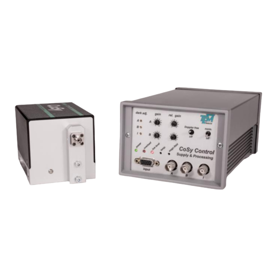
Page 10: Cosycontrol Control Elements
Elimination of hyperfine structure in Doppler background On/off switch for division by signal I („normalisation“) On/off switch for the weighted subtraction of A and B channels Connector outlet to CoSy measurement head which reveals the hyperfine structure Trim potentiometer for cell temperature... - Page 11 CoSy User Manual Fig. 2.3.2.2 Control elements on CoSyControl rear panel informations regarding fuse and supply voltages Fuse holder (inside the power switch housing) Input connector for option „Coil“ Power switch Outlet for cell temperature monitor Outlet for power cord Safety warning table 3.2.2.2: description of CoSyControl rear panel elements...
-
Page 12: Cosycontrol Block Diagram
CoSy User Manual 2.2.3 CoSyControl block diagram Fig. 2.4 Block diagram of CoSyControl 12 (27) -
Page 13: Mechanical Setup And Electrical Connections
If you wish, see chapter 5 first for easy optical adjustment. As the signals generated in the CoSy measurement head depend on the local magnetic flux density, the head must be positioned far enough from magnetised objects such as magnets, optical isolators, etc. - Page 14 CoSy User Manual Fig. 3.1: diagram of connections 14 (27)
-
Page 15: Optical Adjustment Of Cosy Measurement Head
• Fix a straight metal bar with rectangular cross-section to the table for a physical reference line. • Put the CoSy head flat on the table, the lower edge of one of the long sides coinciding with the reference line (position a). -
Page 16: Operating The Cosy System
(see Tab. 2.1: absorption wavelength of certain alkali metals). Synchronise the trigger for the oscilloscope´s horizontal coordinate with the frequency modulation of your laser. (If this is TOPTICA´s DL100 diode laser, connect the trigger output of the scan generator SC110 to the oscilloscopes trigger input.) -
Page 17: Sensitivity Adjustment
Now unblock the laser beam. The “I” output of CoSyControl should now show a constant voltage well between +1V and +10V. If not, change the gain by the range switch on the CoSy measurement head such that the voltage is in this range. (By turning the switch clockwise, the sensitivity of the measurement head and thus the “I”... -
Page 18: Doppler Free Absorption Signal
CoSy User Manual Fig. 5.3: Signals A and B without offset after gain adjustment 5.6 Doppler free absorption signal Bring the “Doppler free” switch into upper position. On the oscilloscope you see a weighted difference of the previously shown signals now (Fig. 6.6 ). -
Page 19: Normalisation
CoSy User Manual Fig. 6,7: Absorption signals with the weighting adjusted correctly (left), and after slight correction of the gain (right) 5.7 Normalisation Now bring the “norm.” switch into the upper position.On the oscilloscope you see signals the amplitude of which is independent of input laser power for a large range of the latter. -
Page 20: Option „Coil" For Magnetic Stray Field Compensation
CoSy head relative to the magnetic field of the earth. If you wish to see the undisturbed spectrum, remove the magnetic elements causing the field or else compensate for it. The version “Coil” of the CoSy- system is useful here. -
Page 21: Further Hints
The center position corresponds to temperature of 45°C. Please note that the CoSy head is equipped with a cell heater, which will not be able to reduce the temperature to a value below room temperature. If the degree of absorption is already higher than 60% at the given room temperature, ask for a CoSy-system containing a shorter cell. -
Page 22: Adapting Cosycontrol To A Given Supply Voltage
Fig. 8.2.1: signal at connector cell temp monitor vs. cell temperature 7.3 Adapting CoSyControl to a given supply voltage The CoSy Control is equipped with an automatic line voltage switch. The CoSy can operate at supply voltages of 115V and 230V 50-60Hz. -
Page 23: Troubleshooting
Check the fuse and replace it by a fuse 250 V, 0,63 A, FLINK(for 110 V:250 V/2A). Neither signal A nor a)Optical adjustment of a) Adjust position of CoSy signal B resembles an CoSy-measurement measurement head. absorption spectrum head is wrong... -
Page 24: Appendix
CoSy User Manual 9 Appendix 9.1 Technical specifications Glas cell dimensions (diameter x length): 25 mm x 25 mm (25 mm x 15 mm on request) Glas cell contains the following elements: (other elements on request): • Rubidium (Rb), • Potassium (K) and •... -
Page 25: Maintenance And Care
CoSy User Manual grounded wall socket. Use the corresponding cable for your country if you have different mains power wall sockets. HD15-connector and HD15-cable The HD15-cable for connecting the CoSy-measurement head to CoSyControl has the following pin out: signal a signal b... -
Page 26: Customer Service
CoSy User Manual 9.4 Customer service In case of nessecary repairs or warranty claims you will obtain fast and reliable help under the address given on page 2. 26 (27) -
Page 27: Subject Index
CoSy User Manual 10 Subject index coil CoSyControl front panel 10, 11 glass cell housing magnetic field 6, 20 Mechanical setup On/off switch Optical adjustment 15, 23 photo diode photo diode amplifier power switch rear panel 10, 11 Rubidium saturation spectrum...
Need help?
Do you have a question about the CoSy and is the answer not in the manual?
Questions and answers