
Related Manuals for AES Saci E-Winner 150

Summary of Contents for AES Saci E-Winner 150
- Page 1 Saci E-Winner 150 Variable Speed Swimming Pool Pump INSTALLATION AND MAINTENANCE MANUAL 01284 658770...
-
Page 2: Table Of Contents
CONTENTS 1. Safety rules ......................................2. Technical data ....................................3. Installation and assembly ................................4. Electrical connections ..................................5. Screen format ...................................... 6. Main screen ......................................7. Operation mode ....................................8. Start-up ........................................9. Setup menu (schematic) ................................10. Setup Menu ...................................... -
Page 3: Safety Rules
1. SAFETY RULES Before installing and using the product: - Carefully read the whole of this manual. - Check that the data indicated on the plate is desired information and is appropriate for the installation, and in particular that the nominal voltage of the pump is compatible with that of the installation. - The installation and maintenance must be carried out solely and exclusively by authorised personnel, responsible for making the electrical connections in accordance with the current safety regulations. -
Page 4: Technical Data
2. TECHNICAL DATA Nominal values: Power supply voltage (V) 220-240 V (1~ - 50/60Hz) Operating speed (RPM) 600 r.p.m – 3000 r.p.m Maximum current (A) Protection rating IP 55 Limits of use: - Minimum ambient temperature: -10ºC - Maximum ambient temperature: +40ºC - Variation in the supply voltage: +/- 10% 3. -
Page 5: Electrical Connections
4. ELECTRICAL CONNECTIONS Power supply 230Vac (1~ 50/60Hz) Digital input 2 Digital input 1 Motor 3x230V Screen Circuit Signal Description When wall-mounted, as there is no cooling from the motor’s own fan, the ventilation system of the wall mounting shall be used for this cooling. This output is at 24Vdc and is activated whenever the pump is running. -
Page 6: Screen Format
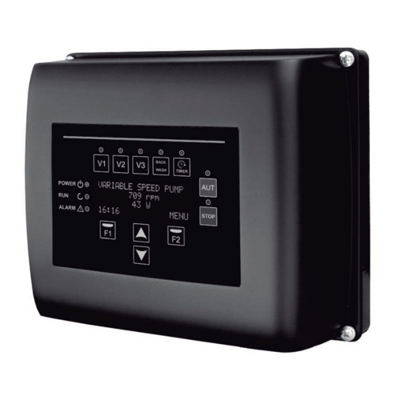
5. SCREEN FORMAT Function Timed pump activation at speed 1 Timed pump activation at speed 2 Timed pump activation at speed 3 To activate the normal operation of the pump To disable the pump at any time STOP To initiate the filter cleaning cycle (back wash) BACK WASH Direct access to the configuration of filtration cycles and schedules TIMER... -
Page 7: Main Screen
6. MAIN SCREEN This screen will show the current status of the pump: e n u It can directly view the instantaneous rotational speed of the motor and the instantaneous consumption of motor. From this screen, if you click on the keys ( ) or ( ), you can directly access the display menu. -
Page 8: Start-Up
8. START-UP The first time you apply voltage to your unit, you will see parameter 1.1 that belongs to menu 1.General Config, which at the same time is the start-up wizard. You will also see this screen if you restore the factory settings. In this menu, enter the basic parameters of the installation prior to programming the time intervals that you wish to have the pump filtering. -
Page 9: Setup Menu (Schematic)
9. SETUP MENU (SCHEMATIC) MENU GENERAL FILTER FIXED ADVANCED MANUAL ALARM CONFIG. FILTRATION WASH SKIMMING SPEED INPUTS CONFIG. MODE DISPLAY HISTORY RESETS 2.1 NUMBER OF 5.1 SKIMMING 7.1 DIGITAL 8.6 LOW WATER 10.1 MODULE 12.1 RESET LANGUAGE BANDS WASH SPEED DURATION SPEED V1 INPUT 1... -
Page 10: Setup Menu
10. SETUP MENU 1. GENERAL CONFIG VALUES Par. Description Notes Units Default Min. Max. To define the language used to interact with the LANGUAGE English variator. SET TIME To adjust the date and time of the variator. Modify the motor rotation direction, if it is rotating ROTATION DIRECTION anticlockwise. - Page 11 VALUES Notes Par. Description Units. Default Min. Max. 2.86 00:00 Sets the start time of band 1. 2.87 24:00 Sets the end time of band 1. EDIT BAND SUNDAY (1) 2.88 1400 3000 Sets the rotational speed of band 1. 2.89 00:00 Sets the start time of band 2.
- Page 12 3. FILTER WASH VALUES Par. Description Units. Notes Default Min. Max. Sets the speed of the pump for the filter cleaning 3.01 WASH SPEED 3000 3000 process. 3.02 WASH DURATION Pump operating time during the filter wash process. Once the filter is clean, the operating time of the 3.03 RINSE DURATION pump for rinse the remaining dirty water from the...
- Page 13 6. FIXED SPEED VALUES Par. Description Notes Units. Default Min. Max. 6.01 SPEED V1 3000 Set the speed at which the pump is to run at speed V1. 6.02 SPEED V2 1400 3000 Set the speed at which the pump is to run at speed V2. 6.03 SPEED V3 3000...
- Page 14 8. ADVANCED PARAMETERS VALUES Notes Par. Description Units. Default Min. Max. Enables the constant monitoring of the pump 8.06 LOW WATER LEVEL ALARM ACTIVE running dry, if this occurs. Value used in the mathematical algorithm that 8.07 LOW WATER ALARM LIMIT calculates the pump running dry.
- Page 15 9. MANUAL MODE The objective of this screen is to test the pump operation, at a specific speed, for a controlled time, to correctly select the operating speeds of the cycles in section 2 of the settings menu. Press F2 to activate the pump initially for 2 minutes at the maximum frequency of the pump. Each time you press the F2 key increases the operating time on a scale of 2 minutes, 15 minutes, 30 minutes, 1 hour, 2 hours, 4 hours or 8 hours.
-
Page 16: Alarms
11. ALARM LOG Shows a log of anomalies of the pump where the speed variator is connected, indicating the date, the time and the anomaly that occurred. This information is very important for detecting possible anomalies in the functioning of the installation. 12. -
Page 17: Warranty
Message Reasons Solution(s) The motor is communicated/disconnected. Check that the cables to the motor are properly connected, as the variator is not detecting the motor, or it is burnt out. ALARM F06 MOTOR FAULT Loss of synchronism. There may also be a loss of synchronism of the motor during operation due to a significant, quick change in the pumping conditions. - Page 18 Cat. MNe150 Rev. 12-02-2024...
Need help?
Do you have a question about the Saci E-Winner 150 and is the answer not in the manual?
Questions and answers