Table of Contents
Advertisement
Advertisement
Chapters
Table of Contents

Related Manuals for AES EFI Series

Summary of Contents for AES EFI Series
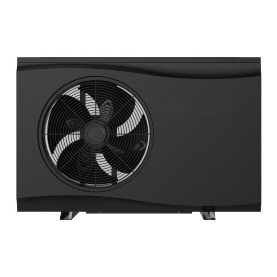
- Page 1 Eco Full Inverter Swimming Pool Heat Pump...
- Page 2 EFI Series Heat Pumps...
- Page 4 THANK YOU Dear Customer, Thank you for choosing our products and greatly we appreciate your confidence in Full Inverter These are the ECO Swimming Pool Heat Pumps for heating or cooling your pool and extending your swimming season. This is a special Pool heat pumps which has been designed to be as Eco friendly as possible, using market leading technology and experience.
- Page 5 Please read carefully...
-
Page 6: Table Of Contents
TABLE OF CONTENT INTRODUCTION ............................2 This manual ............................2 The unit ............................2 SAFETY INSTRUCTIONS ..........................3 ITEMS INSIDE PRODUCT BOX ........................6 OVERVIEW OF THE UNIT..........................7 Unit Dimension ..........................7 Explode View ............................ 8 INSTALLATION ............................10 Installation information ........................10 Condition of installation........................10 Installation place ..........................10 To perfect your installation .......................10... - Page 7 TROUBLESHOOTING..........................26 ENVIRONMENTAL INFORMATION ......................27 DISPOSAL REQUIREMENTS ........................27 WIRING DIAGRAM ...........................28 Specification............................29 ENVIRONMENTAL INFORMATION.......................30 DISPOSAL REQUIREMENTS ........................30 User Manual for APP..........................34 READ THIS MANUAL CAREFULLY BEFORE STARTING UP THE UNIT. DO NOT THROW IT AWAY. KEEP IT IN YOUR FILES FOR FUTURE REFERENCE. BEFORE OPERATING THE UNIT, MAKE SURE THE INSTALLATION HAS BEEN CARRIED OUT CORRECTLY BY A PROFESSIONAL DEALER.
-
Page 8: Introduction
INTRODUCTION This manual This manual includes the necessary information about the unit. Please read this manual carefully before you use and maintain the unit. The unit The swimming pool heat pump is one of the most economical systems to heat the swimming pool efficiently. -
Page 9: Safety Instructions
Safe use The swimming pool heat pump works without oil, gas (petroleum) or other hazardous substance which avoid potential risk that goes together. Moreover no gas (petroleum) connection or a fuel tank is needed. No risk of intoxication, smell or pollution from leakage of such chemicals. ... - Page 10 please take measures (like sufficient ventilation) to prevent the asphyxia caused by the leakage of refrigerant. Use the specified electrical wires and attach the wires firmly to the terminal board (connection in such a way that the stress of the wires is not applied to the sections). Unit must be installed according to AS/NZS 3000:2018 wiring rules and the electrical connection must be complete by a licensed electrician.
- Page 11 get wet and be damaged. Do not clean the unit when the power is ‘ON’. Always shut ‘OFF’ the power when cleaning or servicing the unit. If not, it could cause an injury due to the high speed running fan or an electrical shock. Do not continue to run the unit when there is something wrong or there is a strange smell.
-
Page 12: Items Inside Product Box
ITEMS INSIDE PRODUCT BOX Before starting the installation, please make sure that all parts are found inside the box. The Unit Box Item Image Quantity Eco Full Inverter Swimming pool heat pump Installation and Operation Manual Barrel Unions (40mm) Winter Cover Rubber foots for anti-vibration Water Drainage Pipe... -
Page 13: Overview Of The Unit
OVERVIEW OF THE UNIT Unit Dimension EFI 21 MODEL EFI 17 EFI 14... -
Page 14: Explode View
Explode View Name Name Top Cover Bottom Panel component Electric box cover Inverter compressor Support frame Middle-pressure switch Electronic control components Low-pressure switch Fin heat exchanger Power waterproof cover Fan blade Controller Middle panel Right panel AC fan motor Needle valve Four-way valve Front Panel High- p ressure valve... - Page 15 Reactance Balance tank...
-
Page 16: Installation
INSTALLATION Installation information The following information given here is not an instruction, but simply meant to give the user a better understanding of the installation. Condition of installation The following information given here is not an instruction, but simply meant to give the user a better understanding of the installation. - Page 18 To channel condensation flows, we recommend that you install our condensate drain kit. For this purpose the heat pump must be raised by at least 10 cm. How to install the condensate drain kit? 1. Install your heat pump by raising it by at least 10 cm using solid, moisture-resistant studs. 2.
-
Page 19: Electrical Connection
The filter must be cleaned regularly to ensure that the water in the system is clean and to avoid any problems related to dirt or clogging of the filter. Electrical connection Electrical supply must correspond to that indicated on the appliance. Unit must be earthed Wiring must be completed by a licensed electrician Set leakage protector according to local code... - Page 20 refer to below table: Cable size Heat pump EFI 14 3x2.5mm /AWG 14 EFI 17 3x2.5mm /AWG 14 EFI 21 3x4.0mm /AWG 12 The above wiring information is to be used as a guide only. Electrical connection must be made in accordance AS/NZS 3000:2018 wiring rules.
-
Page 21: Trial Running
Trial running After connecting water to the pool system, complete with a suitable by-pass and electrical connections by a qualified electrician. Be sure that: 1) Appliance is horizontal and on a firm base. 2) Water circuit is well connected (no leaks) 3) Electrical circuit is well connected (all cables tightened correctly at terminals and intermediate circuit breaker), insulated and earthed correctly. -
Page 22: Controller Instruction
Controller Instruction General Input Voltage:DC12V RS485 Communication Short-Press for 1~5seconds,Long-Press for 5 seconds. No Button press for more than 30s,controller surface will exit to original normal. User can operate the controller only when the creen is light on. Back light of Screen is orange,characters and symbols are black. Operation temperature range for controller is -30~70℃。... - Page 23 Increase:Tempreature set + or previous one Decrease:Temperature set - or next one Boost Running mode:Short-press to enter into Smart Running mode:Short-press to enter into Silent Running mode:Short-press to enter in Intructions for Display Symbols :Heating Pool mode :Cooling Pool mode :...
-
Page 24: Instruction For Function
shows 0. When heat pump has error warning,symbol displays and twinkles, water in area displays P or E, water out area displays Error code. Instruction for Function Switch Modes When heat pump is on,short-press to switch Heat/Cool/Auto,each mode is available for selecting Boost/Smart/Silent three modes. -
Page 25: Function Diagnosis
When on status of Parameter Setting , display two“88”,it is asking you to enter your password, press to select, press to confirm.When password is right, displays Parameter No. Displays related parameter value. When on status of Debugging , displays the Number, 01 water pump debugging, 02 testing mode, and displays ON or Off. -
Page 26: Parameter Checking And Adustment
PARAMETER CHECKING AND ADUSTMENT Parameter list Some parameters can be checked and adjusted by the controller. Below is the parameter list. Name Instruction Compressor running Frequency Current hz EEV Open degree Current Value/5 ℃ Current Ambient Temperature ℃ Current Outlet Water Temp. ℃... - Page 27 3.Clean or change a new filter. 2.Check if flow switch is blocked or Flow switch failure; damaged; Water system block. 3.Check if“Y”Shape filter blocked. 1.Check if water flow is not enough or 1.Water flow is too small water pump flow is not enough; 1.Reinject water or change to a new pump of larger water flow;...
- Page 28 sensor temperature TP1 exhaust gas deviation or temperature Check sensor resistance value or if sensor failure Change sensor or re-connect sensor cuts cuts cable coil Change sensor or re-connect sensor temperature Check sensor resistance value or if temperature cable deviation or cuts sensor cuts sensor failure ambient...
- Page 29 Compressor start failure Compressor lack-phase IPM module reset Compressor over-current module extra high temperature Current detection Circuit failure out of step module temperature sensor abnormity communication failure IPM module extra high temperature module temperature sensor failure reserved adjustment data adjustment data input voltage...
-
Page 30: Maintenance The Unit
frequence limits Failure motor drive MAINTENANCE THE UNIT To protect the paintwork, avoid leaning or putting objects on the device. External heat pump parts can be wiped with a damp cloth and domestic cleaner. (Attention: Never use cleaning agents containing sand, soda, acid or chloride as these can damage the surfaces.) To prevent faults due to sediments in the titanium heat exchanger of the heat pump, ensure that the heat exchanger cannot be contaminated (water treatment and filter system necessary). -
Page 31: Winter Shutdown/Lay-Up
Winter Shutdown/Lay-up If there is a chance of frost after the swimming season has ended when the swimming pool heating is switched off and the external temperature is expected to drop below the operating limit, the water circuit of the heat pump should be completely drained. Otherwise, suitable constructional measures should be taken by the customer to protect the heat pump against damage from frost. -
Page 32: Troubleshooting
TROUBLESHOOTING This section provides useful information for diagnosing and correcting certain troubles which may occur. Before starting the troubleshooting procedure, carry out a thorough visual inspection of the unit and look for obvious defects such as loose connections or defective wiring. Before contacting your local dealer, read this chapter carefully, it will save you time and money. -
Page 33: Environmental Information
ENVIRONMENTAL INFORMATION This equipment contains fluorinated greenhouse gases covered by the Kyoto Protocol. It should only be serviced or dismantled by professional trained personnel. This equipment contains R32 refrigerant in the amount as stated in the specification. Do not vent R32 into the atmosphere: R32, is a fluorinated greenhouse gas with a Global Warming Potential (GWP) = 675. -
Page 34: Wiring Diagram
WIRING DIAGRAM Please refer to the wiring diagram on the electric box. Model: EFI 14/17/21... -
Page 35: Specification
Specification Model EFI 14 EFI 17 EFI 21 Heating Capacity (kW) 14.3 17.4 21.2 Advised Pool Volume (m3) 30-50 40-60 50-70 Working Air Temp ℃ ~ 43 ℃ Performance Condition Air 26 ℃ Water 26 ℃ , Humidty 80% Heating Capacity (kW) 14.3 17.4 21.2... -
Page 36: Environmental Information
Package Dimensions(mm) 1080 x 435 x 800 1080 x 435 x 800 1161 x 490 x 855 Recycling ENVIRONMENTAL INFORMATION This equipment contains fluorinated greenhouse gases covered by the Kyoto Protocol. It should only be serviced or dismantled by professional trained personnel. This equipment contains R32 refrigerant in the amount as stated in the specification. - Page 38 User Manual for APP Application – EFI Full Inverter Series...
- Page 39 CONTENT ........................34 Download the APP ............................36 Register ........................37 Configuration of APP .......................... 41 Operation of APP...
-
Page 40: User Manual For App
PLEASE DO NOT THROW IT AWAY. KEEP IT IN YOUR FILES FOR FUTURE REFERENCE. Download the APP Method 1 Android system: Scan the QR code through Browser of Android system. Download the APP and install it. ISO system: Scan the QR code to download the APP and install it. Method 2 Android system: Please browse the internet site http:/47.254.152.109:8080/scadaiot/downFile/execute.do... -
Page 42: Register
Register Please confirm mobile is already connected to the valid Wi-Fi. Open the APP. Please press Register to sign up first time. Type your email address, and press Next. -
Page 43: Configuration Of App
Please input all the items including Email address, Username, Password and Password confirm, and press Finish for sign-up. After sign up successfully, the interface will change to Log in interface automatically. Notes: The password should be only combined with alphabet and numbers. Configuration of APP Input Email address or Username, password and press Sign in button. - Page 44 Press button Connect heat pump, and the interface will be change to next interface. According to the introduction in the interface, please operate. After the heat pump unit setting, please press Next.
- Page 45 Please in this interface, select your router in your home LAN. Input your router’s password, and please click Binding and Next.
- Page 46 In this interface, first, please give your heat pump names as you want. Press the button click here to set Wi-Fi. For Android system, the interface will directly skip to setting menu of mobile to select HF-LPB130. For ISO system, please manually enter the setting menu of mobile to select HF-LPB130. Till now, the connection is finished between mobile and heat pump unit successfully;...
-
Page 47: Operation Of App
Operation of APP Main icons and functions Setting button Operating mode and function icon Setting temperature icon Ambient temperature Temperature setting bar Mode setting button Inquire button Fault button Function setting button On/Off button... - Page 48 Add heat pump unit button Refresh button...
- Page 49 Button introductions Setting Press Setting button, the interface will be changed to setting interface as following picture. Through this interface, a. The name of heat pump unit which is connected with your mobile APP can be changed. b. Delete heat pump unit which is already added in your APP. c.
- Page 50 This button is used to select the operating mode which includes Auto, Cooling and Heating. Once press it, the interface will be enter mode selection interface. In this interface, you can set cooling mode, heating mode or auto mode. After selection, press Confirm to confirm. After set the operating mode, in the icon area of mode will display your selection in the left side of the screen.
- Page 51 After set the function mode, in the icon area of mode will display your selection in the left side of the screen. Silence mode Smart mode Boost mode Inquire button Press Inquire button, the inquire interface will be displayed. From this interface, the following current parameter of the heat pump unit will be displayed.
- Page 52 Fault button Press Fault button, and the fault records include history and current error or protection codes will be displayed.
- Page 53 Add heat pump unit Press this button, and the interface will be changed to add new unit interface as the following picture. Please repeat previous introduction finish the following steps. Refresh button Press this button, the displayed current setting temperature and ambient temperature in screen will be refreshed.
- Page 54 Tips: 1. If the heat pump unit is already set with Android or ISO system, you want to change ISO or Android system mobile phone, and please following steps: a. Press the adjustment buttons ( ) of heat pump controller at the same time till you hear the prompt sound.
- Page 55 Australian Energy Systems Unit 17/6 Maunder St Slacks Creek Queensland 4127 Phone: 07 3299 2700 Web: www.poolheating.com.au Email: reception@poolheating.com.au...
Need help?
Do you have a question about the EFI Series and is the answer not in the manual?
Questions and answers