
Related Manuals for Stamford PFC3


Summary of Contents for Stamford PFC3
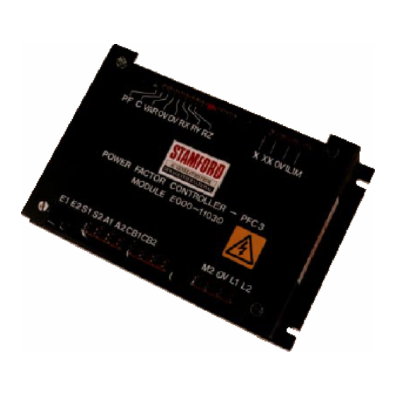
- Page 1 POWER FACTOR CONTROLLER (PFC3) Part No: E000-21030. (PFC3) Part No: E000-22090. Installation and Adjustments Manual.
- Page 2 SAFETY PRECAUTIONS Before operating the generating set, read the generating set operation manual and this generator manual and become familiar with it and the equipment. SAFE AND EFFICIENT OPERATION CAN ONLY BE ACHIEVED IF THE EQUIPMENT IS CORRECTLY OPERATED AND MAINTAINED. Many accidents occur because of failure to follow fundamental rules and precautions.
-
Page 3: Table Of Contents
Remote Switching of Power Factor/VAr Mode - <2> 3.4.3 Generator Current Limiting - <3> 3.4.4 Excitation Voltage Limiting - <4> 3.4.5 Voltage Matching - <5> PFC3 used for Power Factor Correction - Fig 9 SECTION 4 COMMISSIONING AND ADJUSTMENTS Installations Commissioning Basic System 4.2.1 Preliminary Adjustments 4.2.2... - Page 4 Newage International STRONGLY recommends that when a PFC3 is used then "Loss of Excitation" tripping should also be used.
-
Page 5: Section 6 Operation
(or near zero) when operating at leading power factor. Due to its flexibility the PFC3 can be used in many different single or multi-generator power schemes as shown in Fig 1a through Fig 1d and the more unusual applications may not be SINGLE GENERATOR INSTALLATION covered in this manual. -
Page 6: Principle Of Operation
The PFC3 incorporates the necessary circuits to implement low excitation limiting. The output of a separate excitation voltage The PFC3 is capable of operating in a variety of modes with measuring transducer is fed to the input of the main comparator/... -
Page 8: Voltage Matching Mode
Fig.3 Voltage Matching Mode 2.6 Dead-Band or Dynamic Control Modes The PFC3 can be set to operate in one of two control modes dependent upon the requirements of the installation. In dynamic mode, the output from the PFC3 continually adjusts the AVR set- point in response to the smallest change in power factor (or reactive current). - Page 9 [ BAND ] control as seen on a typical power factor meter. Fig. 4 Dead-Band vs Dynamic Fig 5 (Dead-band Control Action) further explains the operation of the PFC3 when set in dead-band control mode. Fig. 5 Dead-Band Control Action...
-
Page 10: Installation
It is the responsibility of the Generating Set Assembler to ensure that adequate protection systems are installed for Automatic In ALL applications of the PFC3, the AVR and generator MUST Synchronising of AC Generators. be equipped with a standard Quadrature Droop Paralleling kit. -
Page 11: Avr Control Output ( A1 , A2 )
3.4 Installing Options - Fig 8 Voltage Matching - <5> If it is required to expand on the basic use of the PFC3 and to use Under certain operating conditions it is desirable to use the one or more of the built-in options then the following notes apply. -
Page 16: Commissioning And Adjustments
Before starting the generator set the commissioning engineer should first make sure that the user adjustable controls and ALL Installations: selection links on the PFC3 and certain AVR controls are set as follows. - Follow section titled: 4.2 Commissioning Basic System... -
Page 17: Droop Setting
(mains) voltage. • The droop circuit polarity has now been verified and must now be set to a level for the best operation of the PFC3. • Open the generator circuit breaker and stop the set before The Input Voltage Selection should be made appropriate for the proceeding. -
Page 18: Pfc3 Setting
• Check that the voltage matching selection link is set to VMAT If this is not the case then it suggests that the PFC3 C/T is E000 - 21030 (BLACK) only. incorrectly rated (or fitted) and should be replaced by the correct unit before proceeding further. -
Page 19: Current Limiting Option
CT wires with a suitable shorting link. in Fig 8 (feature 3). The phasing of this C/T is important. 13. Connect the mains feeder CT S1 / S2 cables to the PFC3 For power factor correction applications it is usual to have two... -
Page 20: Dead-Band And Dynamic Control Options
4.4 Power Factor Correction With the generator operated as a power factor correction system it will be possible to overload the generator windings with a PFC3 setting of near unity power factor WITHOUT overloading the engine/prime-mover. In this situation the generator has to supply the necessary reactive current to the load in order to correct the mains supply power factor to that set on the PFC3. -
Page 21: Light Emitting Diode (Led) Indicators
PF (or VAr) to drift between wider limits before AVR set-point adjustments are made. ( DEC ) To indicate when the PFC3 is decreasing the AVR set- point in dead-band mode. CW = Narrow Band CCW = Wide Band 5.2 Selection Links &... - Page 22 Fig. 12 PFC3 User Adjustable Controls and Selection Links Part number E000 - 21030 (BLACK) Fig. 13 PFC3 User Adjustable Controls and Selection Links Part number E000 - 22090 (GREEN)
-
Page 23: General
Installations where the generator is operated at a kW rating dependent upon the 'heat' demand from the site. Normal PFC3 setting would be 1.0pf to 0.8pf lag to optimise the utilisation of the generator rating but care must be taken not to export unacceptable levels of VAr to the mains supply. -
Page 24: Trouble Shooting
SECTION 7 TROUBLE SHOOTING Under normal circumstances the operation of the PFC3 is fully The reactive power output (kVAr) of the set is controlled automatic and once commissioned the unit should continue to entirely by the excitation system of the generator (i.e the operate without further attention. -
Page 25: Technical Specification
SECTION 8 TECHNICAL SPECIFICATION Input voltage (50-60Hz) 115 range 110-125v ac Applies to PFC E000 - 22090 (GREEN) 220 range 200-230v ac 5VA 240 range 231-250v ac 277 range 251-290v ac (60 Hz only) Input current PF/VAR sensing 5A CT 2.5VA Current Limit 330mA CT 2.5VA Voltage matching input... - Page 26 REGISTERED OFFICE AND ADDRESS NEWAGE INTERNATIONAL LIMITED, PO BOX 17, BARNACK ROAD, STAMFORD LINCOLNSHIRE, PE9 2NB ENGLAND Tel: +44 (0) 1780 484 000 Fax:+44 (0) 1780 484 100 Website: www.newage-avkseg.com STAMFORD POWER GENERATION WORLDWIDE AUSTRALIA NEWAGE ENGINEERS PTY. LIMITED MEXICO...
Need help?
Do you have a question about the PFC3 and is the answer not in the manual?
Questions and answers