Table of Contents
Advertisement
Quick Links
Advertisement
Table of Contents

Related Manuals for Airlink101 AR504


Summary of Contents for Airlink101 AR504
- Page 1 User’s Manual Model # AR504 Ver. 1A...
-
Page 2: Table Of Contents
1. Introduction ... 3 1.1 Functions and Features ... 3 2. Hardware Installation... 5 2.1 Connect the Router... 5 2.2 LED Description... 6 2.3 Verify Connection to Router... 7 3. Configure the Router ... 10 3.1 Setup Wizard ... 10 4. -
Page 3: Introduction
1. Introduction Congratulations on your purchase of this Broadband Router. This product is specifically designed for Small Office and Home Office needs. It provides a complete SOHO solution for Internet surfing and is easy to configure and operate even for non-technical users. - Page 4 Security Functions • Packet Filter Supported Packet Filter allows you to control access to a network by analyzing the incoming and outgoing packets and allowing or denying them access based on the IP address of the source and destination. • Domain Filter Supported o Lets you prevent users from accessing specified domains through this device.
-
Page 5: Hardware Installation
2. Hardware Installation 2.1 Connect the Router Note: Prior to connecting the router, be sure to power off your computer, DSL/Cable modem, and the router. Step 1 Connect one end of a network cable to the WAN port of the router and connect the other end of the cable to the DSL/Cable modem. -
Page 6: Led Description
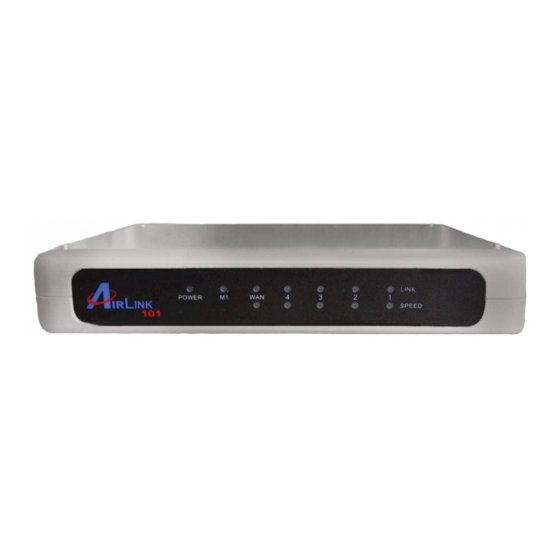
2.2 LED Description Function Power POWER indication System Status status indication WAN port activity Reset Link/Act. Link status Green 10/100 Data Rate Green Color Status Green Device is powered on. M1 flashes once per second to Orange Blinking indicate system is active. M2 is lit when system is busy. -
Page 7: Verify Connection To Router
2.3 Verify Connection to Router Step 1 Go to Start, Run, type command (for Windows 95/98/ME) or cmd (for Windows 2000/XP) and click OK. You will see the command prompt as below. Step 2 Type ping 192.168.1.1 and press Enter. You should get four reply responses back. - Page 8 Step 5 Type ipconfig/renew and press Enter. You should get an IP address of 192.168.1.x (where x is a number between 2 - 254). Proceed to Section 3, Configure the Router. If you don’t get an IP address, reset the router by holding in the reset button at the back of the router for 10 seconds while it is ON and try ipconfig/renew again.
- Page 9 Step 8 After your IP address is released, click Renew. You should get an IP address of 192.168.1.x (where x is a number between 2 - 254). If you don’t get an IP address, reset the router by holding in the reset button at the back of the router for 10 seconds while it is ON and try Renew again.
-
Page 10: Configure The Router
3. Configure the Router 3.1 Setup Wizard Step 1 Open the web browser and type 192.168.1.1 in the URL Address field and press Enter. Step 2 Enter admin for the password field and click Log in. Step 3 Click on Wizard from the main menu to open the Setup Wizard. Step 4 Click Next to begin the Setup Wizard. - Page 11 Static IP If your ISP provided you with a static IP address, select ISP assigns you a static IP address (Static IP Address) and click Next. Proceed to Step 6, Static Cable Modem If you use cable modem, select Obtain an IP address from ISP automatically (Dynamic IP Address) and click Next.
- Page 12 Static IP Fill in the applicable fields according to the information provided by your ISP. Click Next when done and proceed to Cable Modem If your ISP has provided you with a host name, enter it in the Host Name field. If your ISP requires a registered MAC Address, click on the Clone MAC button.
- Page 13 Road Runner Fill in the applicable fields according to the information provided by your ISP. Click Next when done and proceed to Fill in the applicable fields according to the information provided by your ISP. Click Next when done and proceed to Note: Depending on the ISP, you may need to include the domain name with your account name.
- Page 14 PPTP Fill in the applicable fields according to the information provided by your ISP. Click Next when done and proceed to L2TP Fill in the applicable fields according to the information provided by your ISP. Click Next when done and proceed to Step Step...
- Page 15 Step 7 Click Reboot to apply your settings. Step 8 Click OK to confirm reboot. Step 9 Wait for the router to reboot and proceed to Section 4, Verify Connection Status.
-
Page 16: Verify Connection Status
4. Verify Connection Status 4.1 Checking the System Status View the System Status to verify your Internet connection. Step 1 Login to the router’s web configuration page and click on the Status link from the Main Menu. Step 2 Verify that the WAN Status displays valid numbers (instead of all 0’s). If you use Cable modem and you see all 0’s, click on the Renew button. - Page 17 Step 3 Once you clicked the Renew or Connect button, you should see some numbers under WAN Status. This means you have successfully established Internet connection. Note: If you still see all 0’s after clicking on the Renew or Connect button, try the troubleshooting tips at the end of this manual.
-
Page 18: Web Configuration
5. Web Configuration 5.1 Accessing the Web Configuration Utility You may configure the router through the web browser using the Web Configuration Utility. Step 1 Open the web browser and type in 192.168.1.1 and press Enter. Step 2 Enter admin for the password field and click Log in. You will see the Web Configuration Utility’s home page (System Status). -
Page 19: Basic Setting
5.2 Basic Setting 5.2.1 Primary Setup You can set the router’s LAN IP address and change the WAN type (Internet Connection Type) on this page. LAN IP Address: The router’s default IP address is 192.168.1.1. You can change this address to suit your existing network. WAN Type: Displays the current WAN type (Internet Connection Type) selected. - Page 20 Host Name (optional): Some ISPs require a registered host name to connect to their services. Enter the host name provided by your ISP, if applicable. WAN’s MAC Address: Some ISPs require a registered MAC address to connect to their services. Either manually enter the MAC address or click the Clone MAC button. Renew IP Forever: Checking the Enable box will allow the router to automatically renew the IP address automatically when the lease time is expired.
- Page 21 Enter the Account name and Password required to connect to your ISP. Some ISPs require an additional Login Server. Renew IP Forever: Checking the Enable box will allow the router to automatically renew the IP address automatically when the lease time is expired. Click Save to save any changes or click Undo to cancel any changes.
- Page 22 Enter the information provided by your ISP in the respective fields. Connection ID (optional): Some ISPs require the use of a connection ID. Maximum Idle Time (in seconds): Enter the maximum idle time (in seconds) before the router disconnects the PPPoE session. Auto-reconnect (check box): Checking this box enables the router to automatically reconnect to the Internet once the connection is dropped.
- Page 23 Enter the information provided by your ISP in the respective fields. Maximum Idle Time (in seconds): Enter the maximum idle time (in seconds) before the router disconnects the PPPoE session. Auto-reconnect (check box): Checking this box enables the router to automatically reconnect to the Internet once the connection is dropped.
-
Page 24: Dhcp Server
5.2.2 DHCP Server This page allows you to configure the DHCP service of the router. DHCP assigns dynamic IP address to all the network devices connected to the router. DHCP Server: Select either to Enable or Disable the DHCP service (Default is Enable). IP Pool Starting Address: Enter the start of the IP pool range. -
Page 25: Change Password
Clients List The Clients List displays all the DHCP clients currently connected to the router. To perform the first two functions, select a client from the list first. Wake up: Sends a wake up packet to the target client. The target client must support the wake up function. -
Page 26: Forwarding Rules
Old Password: Enter the current login password. New Password: Enter the new login password. Reconfirm: Enter the new login password again. Click Save to save any changes or click Undo to cancel any changes. 5.3 Forwarding Rules 5.3.1 Virtual Server If you want to allow Internet users to access your internal web server or ftp server, you can use the Virtual Server function to open up the ports required to access your internal servers. -
Page 27: Special Ap
Enable (check box): Check on this box to open the port. Use Rule# (optional): Enter the Schedule Rule # you wish to apply to the ID. For more information about using the Schedule Rule #, please see 5.5.6 Schedule Rule. Well known services: You can choose from a list of frequently used services to copy the port number to the Service Ports field. -
Page 28: Miscellaneous
Popular applications: Select from a list of popular applications. Copy to (button): Select the ID # (1 ~ 8) you want to paste the port numbers to first and then click on this button to paste the port numbers to the applicable fields. Click Save to save any changes or click Undo to cancel any changes. -
Page 29: Security Setting
5.4 Security Setting 5.4.1 Packet Filter Packet Filter enables you to control which packets are allowed to pass through the router. Outbound filter applies on all outbound packets. However, Inbound filter applies to packets that are destined to Virtual Servers or DMZ host only. Outbound Packet Filter is the default packet filter page. - Page 30 For source or destination IP address, you can define a single IP address (192.168.1.100) or a range of IP addresses (192.168.1.1001-192.168.1.254). An empty field implies all IP addresses. For source or destination port, you can define a single port (80) or a range of ports (1000-1999).
-
Page 31: Domain Filter
5.4.2 Domain Filter Domain Filter lets you prevent users from accessing any specified domain. Domain Filter: Check the Enable box to activate the Domain Filter function. Log DNS Query: Check the Enable box to log the action of someone trying to access the specified domain. -
Page 32: Url Blocking
5.4.3 URL Blocking URL Blocking will block the local computers from accessing pre-defined web sites. The main difference between Domain filter and URL Blocking is that Domain filter requires you to input a suffix like .com or .org, etc., while URL Blocking only requires you to input a keyword. -
Page 33: Mac Address Control
5.4.4 MAC Address Control MAC Address Control allows you to assign different access rights for different users and to assign a specific IP address to a certain MAC address. MAC Address Control: Check the Enable box to activate the MAC Address Control function. -
Page 34: Miscellaneous Items
5.4.5 Miscellaneous Items Remote Administrator Host/Port: In general, only local users can browse the router’s built-in web configuration utility to perform administration tasks. Remote Administration enables you to perform administrative tasks from remote host. If this feature is enabled, only the host with the specified IP address can perform remote administration. -
Page 35: Advanced Settings
5.5 Advanced Settings 5.5.1 System Time This page allows you to configure the system time of your router. Get Date and Time by NTP Protocol: Select this option if you want to obtain the time from a Network Time Server. Time Server: Select the time server you want to sync with. -
Page 36: System Log
5.5.2 System Log This page allows you to export the system logs to specific destination by means of syslog (UDP) and SMTP (TCP). IP Address for Syslog: Enter the destination IP Address where the syslog will be sent to. Be sure to check the Enable box. IP Address of Outgoing Mail Server: Input the SMTP server IP and port. -
Page 37: Dynamic Dns
5.5.3 Dynamic DNS Dynamic DNS allows any user who wishes to access your server to reach it by a registered DNS name instead of an IP address. Before you enable Dynamic DNS, you need to register an account with one of the Dynamic DNS servers listed in the Provider field. -
Page 38: Routing
5.5.4 Routing The Routing Table allows you to set which network interface address to use for outgoing IP data grams. If you have more than one router and subnet, you will need to configure the routing table to direct the packets to follow the proper routing path so different subnets can communicate with each other. -
Page 39: Schedule Rule
5.5.5 Schedule Rule The Schedule Rule allows you to set the time when certain services will be on or off. Schedule Rule works in conjunction with Virtual Server and Packet Filter to determine when these services will be active or inactive. Schedule: Check the Enable box to activate the Schedule Rule function. - Page 40 Click Save to save any changes or click Undo to cancel any changes. Once you have created the new rule, you can call up this rule from the Virtual Server and Packet Filter page and apply the schedule rule to any IDs in the Virtual Server or Packet Filter page.
-
Page 41: Toolbox
5.6 Toolbox 5.6.1 View Log This page allows you to view the System Log. Back: Returns to the previous page. Refresh: Updates the log. Download: Saves the log to a specified location. Clear logs: Deletes the log from the system. -
Page 42: Firmware Upgrade
5.6.2 Firmware Upgrade This page allows you to update the router’s firmware. 1. Download the latest firmware from the manufacturer’s web site. 2. Click the Browse button to locate the firmware. Be sure to unzip the file first. 3. Click on Upgrade. 4. -
Page 43: Backup Setting
5.6.3 Backup Setting Once you have configured all of the router’s settings, you can backup the settings as a file on your hard drive. (The file will be named config.bin). When you want to restore the saved settings, go to the firmware upgrade page and browse to the config.bin file. 5.6.4 Reset to Default Click OK to restore all settings to factory default. -
Page 44: Miscellaneous Items
5.6.6 Miscellaneous Items Wake-on-LAN is a technology that enables you to power up a network device remotely. In order to use this feature, the target device must be Wake-on-LAN enabled and you have to know the MAC address of the device, i.e. 00-11-22-33-44-55. Clicking the Wake up button will make the router send a wake-up frame to the target device immediately. -
Page 45: Appendix
Turn on the router and wait for the lights on the router to settle down. Step 4 Turn on the computer. Step 5 Redo the Setup Wizard. Step 6 Verify the Connection Status as described in Section 4. Appendix Technical Support E-mail: support@airlink101.com Toll Free: 1-888-746-3238 Web Site: www.airlink101.com...
Need help?
Do you have a question about the AR504 and is the answer not in the manual?
Questions and answers