Table of Contents
Advertisement
Quick Links
Advertisement
Table of Contents

Subscribe to Our Youtube Channel
Related Manuals for LINCHR E Series


Summary of Contents for LINCHR E Series
-
Page 2: Table Of Contents
Contents 1 Revision history ..........................2 2 Introduction ............................. 3 3 Warranty ............................5 4 Instructions for use .......................... 6 5 Technical data ..........................7 6 Installation ............................9 7 Operation Area 8 System connectivity ........................24 9 Charging process ..........................37 10 Power management with external meter interface .............. -
Page 3: Revision History
1 Revision history Version Release date Authors Notes V1.0 Sep . 2021 LINCHR R & D Department Initial filing... -
Page 4: Introduction
Due to the continuous updates of the product, the charging wallbox producer has the right to update the product when necessary. The copyright of th e manual belongs to LINCHR. No copy of the manual without any formal agreement. 2.1.2 About safety The product applies with the state of the art technique and the conforms to safety and health regulations. - Page 5 No cable adapter, patch or cord set extension is allowed for the wallbox cord set. It is strictly forbidden to bypass protection devices, safety or monitoring equipment, move, modify or bridging connect the charging wallbox Reconfiguration or modification of the product is strictly prohibited. The product can only be operated under the permitted conditions.
-
Page 6: Warranty
3 Warranty The warranty period of the charging station is specified by the official LINCHR selling conditions. Prerequisites for product warranty coverage is to observe the instructions in the user manual and to ensure trouble-free and safe use of the product.. - Page 7 4 Limits of use This charging wallbox is an electrical equipment designed for charging battery electric vehicles (BEV). The plug and the socket is compliant to IEC 62196 (alternating current charging, MODE 3) The charging wallbox is suitable for indoor and outdoor usage. If the product is faulty or damaged, please contact a technician and inform the manufacturer.
-
Page 8: Technical Data
5 Technical data Product Information ES-07-C ES-07-B ES-22-C ES-22-B Model Power 3.5-7kW 3.5-7kW 3.5-22kW 3.5-22kW MODE 3 CASE C MODE 3 CASE B MODE 3 CASE C MODE 3 CASE B Charging Mode (with cable) (with socket) (with cable) (with socket) Connector Type 2 Type 2... - Page 9 Earth Leakage DC Leakage (6mA) DC Leakage (6mA) DC Leakage (6mA) DC Leakage (6mA) Protection AC Leakage (30mA) AC Leakage (30mA) AC Leakage (30mA) AC Leakage (30mA) RFID Card RFID Card RFID Card RFID Card Start Charging OCPP Control OCPP Control OCPP Control OCPP Control LED Light belt (red, blue,...
-
Page 10: Installation
6 Installation The following paragraphs describe the charging wallbox installation process. The installation must be performed by qualified personnel only. 6.1 Installation conditions and Environmental requirements The charging wallbox can be used outdoors. Pay attention to the operating environment to meet the equipment operation, otherwise it will affect the service life of the equipment. - Page 11 The rated current of the short-circuit protection device is recommended to be 40A if the charging post is operating at full load, otherwise the charging station will probably not operate properly. It is mandatory to install a circuit breaker with C or B curve, 40A, before the charging input.
- Page 12 For single-phase charging wallbox, in a power supply system with a neutral line, the voltage between the phase line and the neutral line can not be higher than the rated voltage requirement (240VAC). In a power supply system without a neutral line, the voltage between the phase line and the phase line can not be higher than the constant voltage requirement (240VAC).
- Page 13 Install the front housing: Fit the front housing. Install the metal cover protector and tighten the 2 screws on it. Drilling the holes: Lean the mounting template against the wall. It is recommended to set the centre of the template 1500mm above the ground.
- Page 14 Insert the four expansion bolts into the four holes to the ends. Use hands or hammer to make sure the bolts insert to the end of the holes.
- Page 15 Step Description Picture Remove the metal cover (to protect the black front housing, do not remove directly). Remove the black front housing of the charging station (move the two black locks on the back cover of the charging station left and right at the same time). Remove the anti-theft screw on mounting metal...
- Page 16 Step Description Picture Make sure input cable is not connected to the power supply!. Open the wire cover. Insert the power supply cables into the bottom inlet hole. Connect the cables according to the signs on the wire cover scheme. Noted that there is no device to fix the input cable inside the charging wallbox.
- Page 17 6.9 Installation on the stand If the user choose to install charging station on the pedestal instead of wall(provided by the supplier, dedicated pedestal) , please follow the instructions below. Please note that the installer needs to provide the matching screws and other accessories according to different installation sites in the installation..
- Page 18 Step Description Picture Insert the column vertically through the M10 expansion bolts mounting platform. Secure the column with M10 screws and flat pads. Pass one M6 x 20 screw through the bottom of the column for grounding. Remove wall-mounted metal plate on the back of the charging wallbox.
- Page 19 Step Description Picture Install the charging station on the backing plate. Align the position of the charging station and the backing plate, slide the charging station from top to bottom and insert it completely into the backing plate. Secure the charging station and the backing plate with anti-theft screws to ensure reliable installation of the charging...
- Page 20 Step Description Picture Put the wire cover back in place and screw up the 4 screws . Close the black front housing. The installation is finished. Important note : Be sure to use the device after the black cover is correctly assembled.
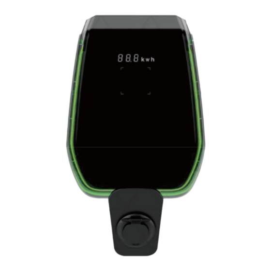
- Page 21 7 Operation The EV can start charging after the charging wallbox is installed. The following chapter describes the operating elements and the display/indicators elements of the charging wallbox. 7.1 Display Areas There are three display areas AREA1, AREA2, AREA3 on the front cover. The function of each AREA is shown as below: Display Type...
- Page 22 Display Type Function description Area The rectangle RFID card active zone shows the card and the AREA3 Tap RFID card area charging wallbox connecting status. Front A LED belt is placed all around the charging wallbox and assumes cover LED indicator different colours to indicate the current status (see table below).
- Page 23 In case of system upgrade operations, the display can show the following messages: Display string format Description 100 UP Upgrade successful E01 UP Upgrade unsuccessful E02 UP The captcha does not match E03 UP Upgrade time out E04 UP Upgrade file error...
- Page 24 7.3 LED indicators (AREA2) The LED indicators give real time information about the charging wallbox status. Four different indicators are explained in the following table: LED indicator Application Description Wifi network Colours and their behaviours (blinking or mode and status steady) show different information: Status Colour...
- Page 25 7.4 Tap RFID card area (AREA3) This is the area where the RFID card is operative. The RFID card is used to start or stop the charging process. The tapping rectangular area within the four light square angles enables the card to perform these operations.
-
Page 26: System Connectivity
8 System connectivity The charging wallbox is equipped with three types of connection interfaces: The Wifi interface: used for configuration purpose (when set to AP mode) and for network-based maintenance/management (when set to STA mode). The RS-485 interface: used to connect to an external meter in order to manage the maximum available power for charging. - Page 27 The Wifi AP (Access Point) mode (also referred as “Hot Spot”) is mainly used for configuration of the parameters and monitor of the charging information. . In this mode, the mobile phone or computer is connected to the Wifi hotspot of the charging station to configure the charging parameters of the charging station and monitor the charging information.
- Page 28 Search for available Wifi networks and connect the charging wallbox’s Wifi hot spot .
- Page 29 Step Description Picture Connect the device (PC, Tablet, Smartphone) to the Wifi network of the charging wallbox (The name of charging wallbox Wifi 050xxx-yyy). Now the connecting device is connected to the charging wallbox Wifi: The Wifi LED indicator starts blinking, confirming that a device is connected to the charging wallbox’s Wifi.
- Page 30 8.3 Configurations through Wifi AP mode In AP mode, when the user equipment is normally connected to the WiFi of the charging wallbox, the parameters of the charging wallbox can be configured through the web portal. Please refer to the following instructions to use the web portal to configure the charging wallbox parameters correctly (the web portal is divided into user backend and installer backend).
- Page 31 Charging Record Report The user can access the charging record interface to monitor all the changing record of the charging wallbox. The user can return to the user settings interface home page by clicking the “Return” button at the bottom. System Parameter Report Users can check the current parameter settings of the charging wallbox.
- Page 32 Wifi Access-Point Setting This page is the WiFi hotspots the charging wallbox provides. The user can select the WiFi hotspot, enter the password of the WiFi hotspot and connect. Important note: These parameters shall be configured by qualified personnel only. OCPP Address Setting This interface can set the OCPP server address, which is convenient for OCPP...
- Page 33 Load Balance Setting: In this page the load balancing can be configured. Load Balance Switch: load balance activation. Max Current Limit: The maximum current setting of the inbound terminal. CAN Addr: CAN address setting, set the CAN address of the master slave charging...
- Page 34 Installer Interface Instruction(Installer Operation Only) 8.3.2 Step Description Picture Connect the device (PC, tablet, smartphone) to the charging wallbox’s Wifi . Open the internet browser. Connect to the following URL: http://192.168.1.1/admin Enter into the administrator password login interface. Open the “checksum_tool” provided by the manufacturer.
- Page 35 Fault Record Report The administrator can check all the fault records in this page. The administator can return to the home page just clicking on the “Return” button at the bottom of the page. System Parameter Report The user can set basic parameters of charging wallbox in this page, including: ...
- Page 36 RFID Setting In this page the user can find the list of the authorized RFID cards and grant the authorization to new cards. The upper part of the page presents the numbers of the authorized RFID cards. Note : One charging wallbox can associate up to three RFID cards.
- Page 37 OCPP protocol. The current series of LINCHR charging wallbox supports the OCPP 1.6 J version of the protocol. For the configuration of the c hargi n g station’s STA mode, please refer to follow steps.
- Page 38 Step Description Picture Press the button highlighted in the following picture for more than 3 seconds. Wait for the sound (1 sec. duration) from the charging wallbox, which says the change of Wifi mode has been completed. The Wifi indicator will change its colour from blue to green.
- Page 39 o Remote Stop Transaction o Get Configuration o Reset o Change Availability o Change Configuration o Reserve Now o Cancel Reservation o Clear Charging Profile o Get Composite Schedule o Set Charging Profile Unlock Connector Operation initiated by the charge point: o Boot Notification o Status Notification o Heartbeat Authorize...
-
Page 40: Charging Process
9 Charging process Be sure the plug is firmly connected to the EV before starting the charging process.. In the CASE B mode (the charging station with a socket), connect the charging cable to the charging wallbox and then to the EV on the other side. In the CASE C mode (the charging station with a charging cable), connect the cable to the EV. -
Page 41: Power Management With External Meter Interface
10 Power management with external meter interface A dedicated external energy meter can be applied in order to optimize the power management operations. By an external energy metering device (provided as optional) the charging wallbox can detect the available amount of charging power in the main supply network. The charging wallbox adjusts by this means charging power in real time according to the remaining power of other loads. - Page 42 Step Description Picture With a RS-485 bus the external meter is connected to the charging wallbox . Remove the black front housing and the inner wire cover to find RS-485 terminal blocks. The RS-485 wires are connected to the bus connector (terminal block) on the charging wallbox.
- Page 43 Step Description Picture With the setting of the external power meter, the charging station is able to real time monitor the maximum volume of the usable power and the volume of the power used by the other loads in the same network.
-
Page 44: Load Balancing
11 Load balancing Multiple charging wallboxes can be connected to each other within one supply network and share the certain amount of power. Among this multiple charging wallboxes, one charging wallbox, the master charging wallbox, connects to the external meter with RS485 and to the other charging wallbox, slave charging wallboxes, with CAN. -
Page 46: System Upgrade
12 System upgrade To upgrade the system firmware please follow the steps below. Step Description Picture Connect the device (PC, tablet, smartphone) to the charging wallbox Wifi AP Mode. Open the internet browser. Connect to the following URL: ht t p :/ /1 9 2. 1 6 8 ..1 .1/admin Please refer to the chapter 8.3.2 to enter into the update page. - Page 47 Open the “checksum_tool” programme. This software application runs on PCs/Laptops Only. It generates the verification code for login. Drag and drop the upgrade file <name_of_the_upgrade_file>.bin into the red check box of the check_sum_tool interface. Then click the “check” button. A verification code will automatically appear in the“Checksum”...
- Page 48 The upgrade process will last about 20 sec. At the end of the process, a message “XX UP” comes into display, indicating that the upgrade process is successful. The charging wallbox will restart after the successful upgrade and there will appear welcome message on the display finally.
- Page 49 Xi’an TELD LINCHR New Energy Technology Co., Ltd. Company Address: Room 101 , Unit A , No.6 Building, Digital economy industrial park, PuFeng Road, Xi'an Hi- tech Industries Development Zone, Xi'an City, Shaanxi Province, People's Republic of China...
Need help?
Do you have a question about the E Series and is the answer not in the manual?
Questions and answers