
Subscribe to Our Youtube Channel
Related Manuals for SIGMATEK ISE 031


Summary of Contents for SIGMATEK ISE 031
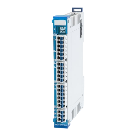
- Page 1 ISE 031 S-DIAS Interface Module RS232 / RS485 / TTY Instruction Manual Date of creation: 23.04.2014 Version date: 26.07.2023 Article number: 20-101-031-E...
- Page 2 (print, photocopy, microfilm or in any other process) without the express permission. We reserve the right to make changes in the content without notice. The SIGMATEK GmbH & Co KG is not responsible for technical or printing errors in the handbook and assumes no responsibility for damages that occur...
- Page 3 1 RS485 interface with switchable termination and spread resistors 1 TTY The S-DIAS ISE 031 interface module has an RS232 interface with the handshake signals RTS and CTS, an RS485 and active TTY interface. Alternatively to the handshake signals, these signals can be configured as a second RS232 interface.
-
Page 4: Table Of Contents
ISE 031 S-DIAS INTERFACE MODULE Contents Introduction ................6 Target Group/Purpose of this Operating Manual ...... 6 Important Reference Documentation ......... 6 Contents of Delivery ..............6 Basic Safety Directives ............7 Symbols Used ................7 Disclaimer ..................9 General Safety Directives ............10 Software/Training ............... - Page 5 Example Connection (starting from HW-Version 3.0) ..... 24 RS485 Guidelines ................ 25 8.3.1 General Data / Specifications ............25 8.3.2 Connection to ISE 031 (up to HW-Version 3.0) ......... 25 8.3.3 Wiring ....................26 RS232 Guidelines ................ 28 8.4.1 General Data / Specifications ............28 TTY Guidelines ................
- Page 6 ISE 031 S-DIAS INTERFACE MODULE 11 Transport/Storage ..............35 12 Storage ...................35 13 Maintenance ................36 13.1 Service ..................36 13.2 Repair ................... 36 14 Disposal ..................36 15 Hardware Class ISE031 ............37 15.1 Interfaces ..................39 15.1.1 General ....................39 15.1.2 Serial Outputs 1-4 ................39 15.1.3...
- Page 7 S-DIAS INTERFACE MODULE ISE 031 15.2.12 GetInfo ....................45 15.2.13 SetBufferRecv ................... 45 15.2.14 ClearRecvBuffer ................45 15.2.15 RtsOnOff ................... 46 15.2.16 rdRts ....................46 15.2.17 rdCts ....................46 15.2.18 DtrOnOff ................... 47 15.2.19 rdDtr ....................47 15.2.20 rdDcd ....................47 15.2.21...
-
Page 8: Introduction
General knowledge of automation technology is required. Further help and training information, as well as the appropriate accessories can be found on our website www.sigmatek-automation.com. Our support team is happily available to answer your questions. Please see our website for our hotline number and business hours. -
Page 9: Basic Safety Directives
S-DIAS INTERFACE MODULE ISE 031 Basic Safety Directives Symbols Used The following symbols are used in the operator documentation for warning and danger messages, as well as informational notes: DANGER Danger indicates that death or serious injury will occur, if the specified measures are not taken. - Page 10 ISE 031 S-DIAS INTERFACE MODULE INFORMATION Information Provides important information on the product, handling or relevant sections of the documentation, which require attention. Page 8 26.07.2023...
-
Page 11: Disclaimer
It does not guarantee properties under the warranty. Please thoroughly read the corresponding documents and this operating manual before handling a product. SIGMATEK GmbH & Co KG is not liable for damages caused through, non-compliance with these instructions or applicable regulations. -
Page 12: General Safety Directives
ISE 031 S-DIAS INTERFACE MODULE General Safety Directives The Safety Directives in the other sections of this operating manual must be observed. These instructions are visually emphasized by symbols. INFORMATION According to EU Directives, the operating manual is a component of a product. -
Page 13: Software/Training
S-DIAS INTERFACE MODULE ISE 031 CAUTION Handle the device with care and do not drop or let fall. Prevent foreign bodies and fluids from entering the device. The device must not be opened! Manipulez l’appareil avec précaution et ne le laissez pas tomber. -
Page 14: Standards And Directives
The product was constructed in compliance with the following European Union directives and tested for conformity. 3.1.1 EU Conformity Declaration EU Declaration of Conformity The product ISE 031 conforms to the following European directives: • 2014/35/EU Low-voltage Directive • 2014/30/EU Electromagnetic Compatibility (EMC Directive) •... -
Page 15: Type Plate
S-DIAS INTERFACE MODULE ISE 031 Type Plate HW: Hardware version SW: Software version 26.07.2023 Page 13... -
Page 16: Technical Data
ISE 031 S-DIAS INTERFACE MODULE Technical Data Performance Data Interfaces 1x RS232 or 2x RS232 1x RS485 1x TTY (20 mA) Adjustable data transfer rates RS232 2400 Baud, 4800 Baud, 9600 Baud, 19200 Baud, 38400 Baud, 57600 Baud, 62500 (starting from HW-Version 1.1), 115200 Baud... -
Page 17: Electrical Requirements
S-DIAS INTERFACE MODULE ISE 031 Electrical Requirements 18-30 V DC Power supply +24 V UL: Class 2 or LVLC Current consumption of the +24 V maximum 100 mA supply Voltage supply from S-DIAS bus +5 V Current consumption on the... - Page 18 ISE 031 S-DIAS INTERFACE MODULE Page 16 26.07.2023...
-
Page 19: Miscellaneous
S-DIAS INTERFACE MODULE ISE 031 Miscellaneous Article number 20-101-031 Standard UL 508 (E247993) Approbations UL, cUL, CE Environmental Conditions Storage temperature -20 ... +85 °C Environmental temperature 0 ... +55 °C Humidity 0-95 %, non-condensing Installation altitude above sea 0-2000 m without derating level >... -
Page 20: Mechanical Dimensions
ISE 031 S-DIAS INTERFACE MODULE Mechanical Dimensions Page 18 26.07.2023... -
Page 21: Connector Layout
S-DIAS INTERFACE MODULE ISE 031 Connector Layout starting with HW Version 4.20 INFORMATION The GND supply (X4: Pin 2 and Pin 3) is internally bridged. Only one GND pin (pin 2 or pin 3) is required to power the module. The bridged connections may be used for further looping of the GND supply. -
Page 22: Status Leds
ISE 031 S-DIAS INTERFACE MODULE Status LEDs Module Status green module active no supply available BLINKING (5 Hz) no communication User yellow can be set from the application (e.g. the module LED can be set to blinking through the visualization so that the module is easily found in the control... -
Page 23: Applicable Connectors
S-DIAS INTERFACE MODULE ISE 031 Applicable Connectors Connectors: X1-X4: Connectors with spring terminals (included in delivery) The spring terminals are suitable connecting ultrasonically compacted (ultrasonically welded) strands. Connections: Stripping length/Sleeve length: 10 mm Plug-in direction: parallel to conductor axis or to PCB Conductor cross section, rigid: 0.2-1.5 mm... -
Page 24: Label Field
ISE 031 S-DIAS INTERFACE MODULE Label Field Manufacturer Weidmüller Type MF 10/5 CABUR MC NE WS Weidmüller article number 1854510000 Compatible printer Weidmüller Type Printjet Advanced 230V Weidmüller article number 1324380000 Page 22 26.07.2023... -
Page 25: Wiring
S-DIAS INTERFACE MODULE ISE 031 Wiring Example Connection 26.07.2023 Page 23... -
Page 26: Example Connection (Starting From Hw-Version 3.0)
ISE 031 S-DIAS INTERFACE MODULE Example Connection (starting from HW-Version 3.0) Page 24 26.07.2023... -
Page 27: Rs485 Guidelines
• External spread and terminating resistors can be used, however, the internally provided resistors can no longer be activated via the application. 8.3.2 Connection to ISE 031 (up to HW-Version 3.0) 120 Ω 26.07.2023 Page 25... -
Page 28: Wiring
ISE 031 S-DIAS INTERFACE MODULE 8.3.3 Wiring • Because the RS485 requires a defined quiescent point, a pull-up and pull-down resistor is required in addition to the termination resistor. These resistors can be placed at any location. The +5 V supply shown in the diagram above is generated externally. - Page 29 S-DIAS INTERFACE MODULE ISE 031 8.3.3.1 Starting from HW-Version 3.0 26.07.2023 Page 27...
-
Page 30: Rs232 Guidelines
ISE 031 S-DIAS INTERFACE MODULE RS232 Guidelines 8.4.1 General Data / Specifications • For RS232 connections, shielded data cables must be used! • Maximum bus participants: 2 participants • Maximum length: 15 m TTY Guidelines 8.5.1 General Data / Specifications •... -
Page 31: Wiring And Configuration
S-DIAS INTERFACE MODULE ISE 031 8.5.2 Wiring and Configuration 8.5.2.1 ACTIVE 8.5.2.2 PASSIVE 26.07.2023 Page 29... -
Page 32: Shielding
The low-ohm shielding is either connected at the entry to the control cabinet or directly before the ISE 031 over a large, low-ohm surface (cable grommets, grounding clamps)! Noise signals can therefore be prohibited from reaching the electronics and affecting the function. -
Page 33: Assembly/Installation
S-DIAS INTERFACE MODULE ISE 031 Assembly/Installation Check Contents of Delivery Ensure that the contents of the delivery are complete and intact. See chapter 1.3 Contents of Delivery. INFORMATION On receipt and before initial use, check the device for damage. If the device is damaged, contact our customer service and do not install the device in your system. -
Page 34: Mounting
ISE 031 S-DIAS INTERFACE MODULE Mounting The S-DIAS modules are designed for installation into the control cabinet. To mount the modules a DIN-rail is required. The DIN rail must establish a conductive connection with the back wall of the control cabinet. The individual S-DIAS modules are mounted on the DIN rail as a block and secured with latches. - Page 35 S-DIAS INTERFACE MODULE ISE 031 Recommended minimum distances of the S-DIAS modules to the surrounding components or control cabinet wall: a, b, c … distances in mm (inches) 26.07.2023 Page 33...
-
Page 36: Supported Cycle Times
ISE 031 S-DIAS INTERFACE MODULE 10 Supported Cycle Times 10.1 Cycle Times below 1 ms (in µs) x= supported 10.2 Cycle Times equal to or higher than 1 ms (in ms) x= supported x= supported Page 34 26.07.2023... -
Page 37: Transport/Storage
S-DIAS INTERFACE MODULE ISE 031 11 Transport/Storage INFORMATION This device contains sensitive electronics. During transport and storage, high mechanical stress must therefore be avoided. For storage and transport, the same values for humidity and vibration as for operation must be maintained! Temperature and humidity fluctuations may occur during transport. -
Page 38: Maintenance
ISE 031 S-DIAS INTERFACE MODULE 13 Maintenance INFORMATION During maintenance as well as servicing, observe the safety instructions from chapter 2 Basic Safety Directives. 13.1 Service This product was constructed for low-maintenance operation. 13.2 Repair INFORMATION In the event of a defect/repair, send the device with a detailed error description to the address listed at the beginning of this document. -
Page 39: Hardware Class Ise031
S-DIAS INTERFACE MODULE ISE 031 15 Hardware Class ISE031 Hardware Class ISE031 for the S-DIAS ISE031 module 26.07.2023 Page 37... - Page 40 ISE 031 S-DIAS INTERFACE MODULE This hardware class is used to control the ISE 031 hardware module with 4 serial interfaces (TTY, RS232 1, 2 and RS485). Starting with FPGA version 2.0 the second RS232 interface can be activated. The pins RTS/CTS of the first RS232 interface are used as TxD 2 / RxD 2.
-
Page 41: Interfaces
S-DIAS INTERFACE MODULE ISE 031 15.1 Interfaces 15.1.1 General Class State State This server shows the actual status of the hardware class. Device ID State The device ID of the hardware module is shown in this server. FPGA Version State FPGA version of the module in the format 16#XY (e.g. -
Page 42: Communication Interfaces
ISE 031 S-DIAS INTERFACE MODULE Max Read Property Here, the maximum read-length in bytes via S-DIAS per cycle is entered. Length no transfer - If Rd and Wr = 0 the interface is deactivated Interface [1-4] standard value maximum size... -
Page 43: Globale Methods
S-DIAS INTERFACE MODULE ISE 031 15.2 Globale Methods The following methods are from the base class of the UART component (_SerLib) and can be called via the SerInterface[1-4] server. 15.2.1 StartUser This function initializes the serial interface according to the input parameters. -
Page 44: Stopuser
ISE 031 S-DIAS INTERFACE MODULE If the function is called in the Init method, the availability of the 9-bit mode cannot be verified, because the FPGA version of the module is read out later. The 9-bit mode can therefore only be called in the Init method if the user is sure that the module has an FPGA version of 1.2 or higher. -
Page 45: Setonline
S-DIAS INTERFACE MODULE ISE 031 15.2.5 SetOnline This function is not used here (relevant for _SerLib). Transfer parameters Type Description State DINT Status disable LASAL communication enable LASAL communication Return parameters Type Description ErrorCode DINT This function is not available here 15.2.6... -
Page 46: Getrecvstate
ISE 031 S-DIAS INTERFACE MODULE 15.2.8 GetRecvState Returns the number of bytes in the receive buffer. Transfer parameters Type Description none Return parameters Type Description length UDINT Number of characters in the receive buffer 15.2.9 GetSendState Returns the number bytes in the send buffer, which still have to be sent. -
Page 47: Getinfo
S-DIAS INTERFACE MODULE ISE 031 15.2.12 GetInfo This function is not used here (relevant for _SerLib). Transfer parameters Type Description Info ^LSLAPI_ Provides information over the serial interface. SERIALINFO Return parameters Type Description ErrorCode DINT This function is not available here. -
Page 48: Rtsonoff
ISE 031 S-DIAS INTERFACE MODULE 15.2.15 RtsOnOff This function sets or deletes RTS at the serial interface (Request to Send). Transfer parameters Type Description State BOOL Status LOW (sending not allowed) HIGH (default: sending allowed) Return parameters Type Description ErrorCode DINT See error codes. -
Page 49: Dtronoff
S-DIAS INTERFACE MODULE ISE 031 15.2.18 DtrOnOff This function is not used here (relevant for _SerLib). Transfer parameters Type Description State BOOL Status HIGH Return parameters Type Description ErrorCode DINT See error codes This function is not available here. 15.2.19 rdDtr This function is not used here (relevant for _SerLib). -
Page 50: Rdri
ISE 031 S-DIAS INTERFACE MODULE 15.2.22 rdRI This function is not used here (relevant for _SerLib). Transfer parameters Type Description none Return parameters Type Description State BOOL Status This function is not available here. 15.2.23 SetRSMode With this method, the mode of the serial interface can be changed in the RS485 interface. -
Page 51: Recvtimingblock
S-DIAS INTERFACE MODULE ISE 031 15.2.25 RecvTimingBlock This function is not used here (relevant for _SerLib). Transfer parameters Type Description Buffer pVoid Pointer to the data buffer (buffer contains the time stamp of each byte received) rdlenght UDINT Number of bytes to read (time stamp) -
Page 52: Cleartimingbuffer
ISE 031 S-DIAS INTERFACE MODULE 15.2.28 ClearTimingBuffer This function is not used here (relevant for _SerLib). Transfer parameters Type Description none Return parameters Type Description State DINT Status This function is not available here. 15.2.29 GetInterfaceTypee The function returns the interface type. - Page 53 S-DIAS INTERFACE MODULE ISE 031 This results in the following possible baud rates: 1 600 4 800 15 360 62 500 1 800 5 120 15 625 76 800 1 920 5 760 18 432 92 160 2 048 6 144...
-
Page 54: Meaning Of The Errorcodes
ISE 031 S-DIAS INTERFACE MODULE 15.2.31 Meaning of the ErrorCodes Message Definition SERERROR_NONE SERERROR_BAUDR Baud rate <> 0-10, when calling the function SetBaudrate, the error code means that the given baud rate is not adjustable. SERERROR_PARITY Parity <> 0-4 SERERROR_STOPBI StStop bits <>... -
Page 55: Internal Properties
S-DIAS INTERFACE MODULE ISE 031 15.3 Internal Properties 15.3.1 Maximum Transfer Rates If the set baud rate is higher than can be fetched per cycle, the receive buffer overflows. Starting with FPGA version 1.5 the receive buffer (from 120 to 784 bytes) and the send buffer (from 120 to 240 bytes) of the hardware have been increased. - Page 56 ISE 031 S-DIAS INTERFACE MODULE Documentation Changes Change date Affected Chapter Note page(s) 18.07.2014 3 Connector Layout Added wiring notice 21.11.2014 1.1 Performance Data Adjustable data transfer rates 30.01.2015 3.2 Applicable Connectors Added note concerning connecting the S-DIAS module while voltage is applied 05.03.2015...
- Page 57 S-DIAS INTERFACE MODULE ISE 031 11.07.2022 1.2 Electrical Requirements Current consumption +5 V corrected 20.04.2023 3 Connector Layout Info box corrected 26.07.2023 Document General chapters added, design 26.07.2023 Page 55...
- Page 58 ISE 031 S-DIAS INTERFACE MODULE Page 56 26.07.2023...
Need help?
Do you have a question about the ISE 031 and is the answer not in the manual?
Questions and answers