
Related Manuals for Arkel ARLINE

Summary of Contents for Arkel ARLINE
- Page 1 Arkel ArLine User Manual V1.24 ARKEL ARLINE REMOTE ALARM, MONITORING AND INTERCOM SYSTEM FOR LIFTS USER MANUAL...
- Page 2 This document has been created to be a guide for Arkel customers. Reproduction, transfer, distribution or storage of part or all the contents in this document in any form without the prior written permission of Arkel is prohibited. Arkel reserves the right to make changes and improvements to any of the products described in this document without prior notice.
-
Page 3: Table Of Contents
..................16 RKEL RKEL ONNECTIONS ARKEL ARLINE-S-TP/ARKEL ARLINE-S-INT DIP-SWITCH SETTINGS ............16 ARKEL ARLINE-S SOUND ADJUSTMENT ........................ 16 10. USING THE BUTTON ON THE ARKEL ARLINE-M ....................16 11. LED INFORMATION ..............................17 11.1. -M LED I ........................17 RKEL NFORMATION 11.2. - Page 4 Arkel ArLine User Manual V1.24 26.2................................32 ND OF LARM 26.3........................32 MERGENCY LECTRIC OWER UPPLY 26.4............................. 32 NFORMATION IN THE LIFT CAR 26.5................................. 32 OMMUNICATION 27. DIMENSIONS ................................... 33 27.1. -M ............................... 33 RKEL 27.2.
-
Page 5: Safety Precautions
• Arkel ArLine is a remote alarm system designed for lifts. It complies with EN 81-28, EN 81-20 and EN 81-70 standards. In addition to the remote alarm system, it can also function as an intercom system as required in EN 81-20. -
Page 6: Technical Specifications
Arkel ArLine User Manual V1.24 Technical Specifications 4.1. Arkel ArLine-M Technical Specifications Mobile Frequency band Quad-Band 850/900/1800/1900 MHz RF output power Class 4 for EGSM 850/900 MHz (2W/33dBm max.) Class 1 for DCS 1800/1900 MHz (1W/30dBm max.) Technology 2G (GSM), GPRS SIM card slot Nano SIM (4FF), 12.30 x 8.80 x 0.67 mm... -
Page 7: Arkel Arline-S-Cop Technical Specifications
Arkel ArLine User Manual V1.24 4.2. Arkel ArLine-S-COP Technical Specifications Inputs Unit supply PWR, GND 10-30VDC (BAT connector Max. 120mA @ 24V DC is not used) External alarm button input ALB1, ALB2 8-30VDC, 5 mA Insulated with double direction optocoupler... -
Page 8: Overview
Under the car Arkel ArLine-M, main unit Arkel ArLine-S-COP, car speech unit Arkel ArLine-S-TP, top of car speech unit Arkel ArLine-S-TP, pit (or under car) speech unit (* 1) Arkel ArLine-S-INT, machine room/control panel intercom Lift control unit Lift control panel... -
Page 9: Overview Arkel Arline-M
CAR: Car alarm unit connection (Inside the car, top of car and under car) 100, 1000: Supply inputs Arkel ArLine-S Supply (PWR, GND): Supply outputs for Arkel ArLine-S units INCOM (COM +, COM-): Supply outputs for programmable inputs IN1-IN5: Programmable inputs... -
Page 10: Overview Arkel Arline-S-Cop
Arkel ArLine User Manual V1.24 5.3. Overview Arkel ArLine-S-COP Arkel ArLine-M (Main unit) connection External alarm button connection Connection of external yellow and green pictogram LEDs Output for external alarm button and pictogram LEDs Volume adjustment trimpot External microphone connection... -
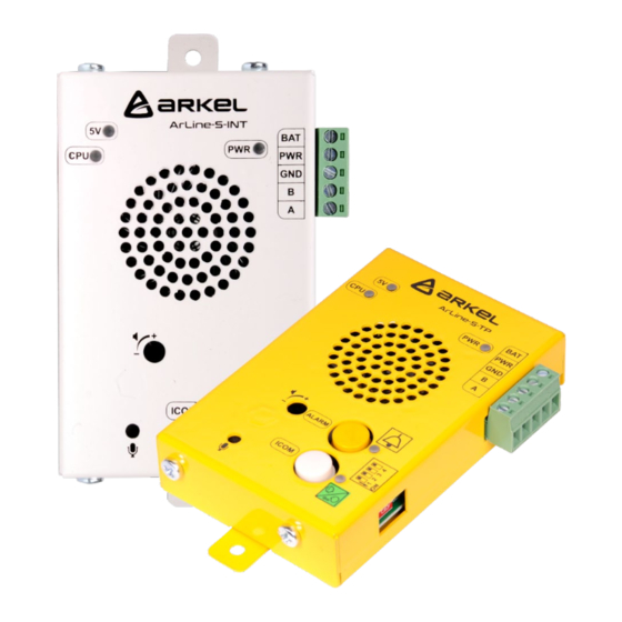
Page 11: Overview Arkel Arline-S-Int
A standard mobile phone can also help with the determination of the installation place. For this purpose, the operator of the mobile phone and the SIM card to be used on the Arkel ArLine-M device must be identical. Place the mobile phone in the area where you intend to install the product. -
Page 12: S-Tp
6.4. Installation of Arkel ArLine-S-INT The Arkel ArLine-S-TP unit is designed to be placed in the machine room or on the lift control panel. There is an intercom button on the unit. It should be located in the area where the emergency rescue operation is to be carried out (In the machine room or on the lift control panel). -
Page 13: Connections
To prevent damage to the product, the GSM antenna must be connected to the connector before the supply. In the “Installation of Arkel ArLine-M” section, information is given about the location of the antenna and the signal strength. +24V DC Supply input. -
Page 14: Arkel Arline-S-Cop Connections
BAT connector is not used, must be left blank. The PWR-GND power supply via the Arkel ArLine-M has battery backup. 24V DC when there is power, 12V DC when there is no electricity. For cable connection, the following must be observed in the travelling cable: Use 4 cables next to each other. - Page 15 In Arcode and ARL-700 control systems, the following method can be used to connect the same contact to both the Arkel ArLine-S-COP and the control system if the single contact alarm button is used. Arkel ArLine-S-COP CPC/CPC-T operating panel board...
-
Page 16: Arkel Arline-S-Tp/Arkel Arline-S-Int Connections
Each Arkel ArLine-S unit connected to the communication line must have a different identity. The units with the same ID do not work. The ID of the Arkel ArLine-S-COP unit is accepted as "00". The ID setting for the other Arkel ArLine-S units is described below. -
Page 17: Led Information
YEL. Yellow Turned on The alarm is active. GRE. Green Turned on The alarm call is taking place. Green Flashing Communication with the Arkel ArLine-M unit. Green Flashing 11.3. Arkel ArLine-S-TP LED Information Color State Description POWER Green Turned on There is an external 12 / 24V DC supply. -
Page 18: Arkel Arline-S-Int Led Information
There are 5 programmable inputs (IN1-IN5) on the Arkel ArLine-M main unit. There are no programmable inputs on the other units. The functions that can be assigned independently to the inputs are listed below. The active when there is signal (NO) or active when there is no signal (NC) function settings can be made via ARKEL Cloud menu. -
Page 19: Output (Relay) Functions
V1.24 Output (Relay) Functions There are 2 programmable relay outputs (OU1-OUT2) on the Arkel ArLine-M main unit. There is no programmable output on other units. The functions that can be assigned independently to the relays are listed below. Relay function... - Page 20 The stages of alarming via the Arkel ArLine-S-TP alarm unit are as follows: • Press and hold the yellow alarm button on the unit for 3 seconds. Alarm filtering is not applied to the Arkel ArLine-S- TP units. Alarm information is transmitted to the recovery service via ARKEL Cloud and optionally via SMS. The yellow •...
- Page 21 Arkel ArLine User Manual V1.24 Is filter active? Is filtered? Is this the first call? Answer? Answer? Initiating voice Rescue service User Answer? comm Answer? Answer? Answer? Figure 16 Alarm flowchart...
-
Page 22: Arkel Arline Parallel Installation
EN 81-20. In addition, in the Arkel ArLine system, two-way communication can be made between all speech units. The ID of the Arkel ArLine-S-INT unit to be used for intercom in the machine room must be set to "04" with the dip-switch (See section Arkel ArLine-S-TP / Arkel ArLine-S-INT Dip-switch Settings). -
Page 23: Automatic Communication Test (3 Days Test)
Arkel ArLine-M. In the Arkel ArLine system, the battery's capacity is tested at regular intervals (1 week). The test can take up to 30 minutes. During the test, the battery alarm is activated when it is determined that the battery capacity, including 15 minutes of talk, is not sufficient to allow the alarm system to run for 60 minutes. -
Page 24: Replacing The Battery
15 minutes after the power cut, the rescue service/personnel is informed of the power cut. When the battery voltage falls below a certain level, the battery is disconnected and the Arkel ArLine-M shuts down to prevent deep discharge damage of the battery in the event of a power failure. -
Page 25: Adding Buildings
Adding Devices To define a new Arkel ArLine device to the building, click on the 'Devices (Arkel ArLine)' link in the main menu on the left side of the screen. Enter the device adding page with the 'Add New Device' button. -
Page 26: Arkel Cloud Arkel Arline Interface
All Arkel ArLine related settings are made via ARKEL Cloud. To access the Arkel ArLine menu, all Arkel ArLine devices connected to the company can be displayed via the 'Devices (Arkel ArLine)' tab in the main menu. Click on the device name to access to the device details. - Page 27 Arkel ArLine User Manual V1.24 The parameter and status information under the “Arkel ArLine Settings” tab is described below. • Under the “Settings” section, the necessary parameters are set for the device Parameters Option Description Filtering Active Alarm filtering is activated. This setting should be selected in normal operation of the device.
- Page 28 The units connected to the lift can be displayed live via the visual section under the status section. The following example illustrates: • With the Arkel ArLine-M device; It is shown that the inside the car, car top and machine room units are connected. • Bottom and pit alarm units are not connected.
-
Page 29: Event Logs
22.5. Adding Emergency Call Recipients The phone numbers to be dialed in the event of an alarm are entered via ARKEL Cloud. To do this, first enter the "Buildings" tab and the buildings connected to the company are displayed. Under the 'Buildings' tab, the building to which the number assignment should be made is selected. -
Page 30: Setting Parameters With Sms
• be set. • To Arkel ArLine-M receive the SMS, “SIM” led must be turned off and “GSM” led must be turned on. If these two led status is not correct, “Errors and Possible Solutions” should be checked. • After sending the SMS, “FILTER”, “GSM” and “INTERCOM” leds on the device will be flashing for 10 seconds. -
Page 31: Setting Parameter With Arem
AutoEOAOpt:Passive Setting Parameter with AREM In order to set parameters over AREM, Arkel ArLine-M board must be connected to CAR CANBUS line. By entering “Tools -> Device Parameters -> ARLINE Settings” menu, parameters can be changed. In order to monitor the parameters and Arkel ArLine-M status;... -
Page 32: Remote Update
Arkel ArLine-M. While the device energizing again with 24V, press the button on the Arkel ArLine-M simultaneously for 5 to 10 seconds. In this case, the device switches to update mode and the update process starts. -
Page 33: Dimensions
Arkel ArLine User Manual V1.24 Dimensions 27.1. Arkel ArLine-M Figure 26 Arkel ArLine-M mechanical dimensions... -
Page 34: Arkel Arline-S-Cop
Arkel ArLine User Manual V1.24 27.2. Arkel ArLine-S-COP Figure 27 Arkel ArLine-S-COP mechanical dimensions... -
Page 35: Arkel Arline-S-Tp
Arkel ArLine User Manual V1.24 27.3. Arkel ArLine-S-TP Figure 28 Arkel ArLine-S-TP mechanical dimensions... -
Page 36: Arkel Arline-S-Int
Figure 29 Arkel ArLine-S-INT mechanical dimensions Short EU Declaration of Conformity With this document, Arkel Elektrik Elektronik San. ve Tic. A.Ş. declares that Arkel ArLine radio equipment product is in compliance with the 2014/53/EU Radio Equipment Regulation. The full text of the EU declaration of conformity is available at:...
Need help?
Do you have a question about the ARLINE and is the answer not in the manual?
Questions and answers