Advertisement
Quick Links
Installation, Operation & Maintenance Manual
TWO POST LIFT
The specifications stated on this brochure are not binding.
We reserve the right to change the specification without notice
ECHNOLIFT
AUTOMOTIVE EQUIPMENT
SL-9
9,000 LBS.
IMPORTANT:
Read this manual completely before
installing or operating lift
Showroom - Distribution Centre
8275, 17e Avenue, Montréal, Qc., Canada H1Z 4J9
1-800-361-4095 • 514-328-2300 • Fax 514-328-4684
Advertisement

Related Manuals for TECHNOLIFT SL-9


Summary of Contents for TECHNOLIFT SL-9
- Page 1 TWO POST LIFT The specifications stated on this brochure are not binding. We reserve the right to change the specification without notice ECHNOLIFT AUTOMOTIVE EQUIPMENT SL-9 9,000 LBS. IMPORTANT: Read this manual completely before installing or operating lift Showroom - Distribution Centre 8275, 17e Avenue, Montréal, Qc., Canada H1Z 4J9...
- Page 2 Installation, Operation & Maintenance Manual NOTES _______________________________________________________________________________ _______________________________________________________________________________ _______________________________________________________________________________ _______________________________________________________________________________ _______________________________________________________________________________ _______________________________________________________________________________ _______________________________________________________________________________ _______________________________________________________________________________ _______________________________________________________________________________ _______________________________________________________________________________ _______________________________________________________________________________ _______________________________________________________________________________ _______________________________________________________________________________ _______________________________________________________________________________ _______________________________________________________________________________ _______________________________________________________________________________ _______________________________________________________________________________ _______________________________________________________________________________ _______________________________________________________________________________ _______________________________________________________________________________ _______________________________________________________________________________ _______________________________________________________________________________ _______________________________________________________________________________ _______________________________________________________________________________ _______________________________________________________________________________ _______________________________________________________________________________ _______________________________________________________________________________ _______________________________________________________________________________ _______________________________________________________________________________ _______________________________________________________________________________ _______________________________________________________________________________ _______________________________________________________________________________ _______________________________________________________________________________ _______________________________________________________________________________ _______________________________________________________________________________ _______________________________________________________________________________ _______________________________________________________________________________...
-
Page 3: Table Of Contents
CONTENTS Product features and specifications...........1 Installation requirement..............3 Steps of installation ...............4 Explosive view................23 Test run..................26 Maintenance………………..............28 Trouble shooting................29 Part list…………………………………………………………………………………………..……….30... -
Page 4: Product Features And Specifications
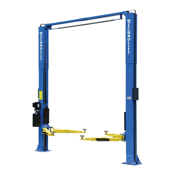
I. PRODUCT FEATURES AND SPECIFICATIONS CLEAR-FLOOR DIRECT-DRIVED MODEL FEATURES Model SL-9 SL-9H (See Fig. 1) · Direct-drived design, minimize the lift wear parts and breakdown ratio · Dual hydraulic cylinders, designed and made as standards, utilizing oil seal in cylinder ·... - Page 5 Arm Swings View For Model SL-9 SL-9H 1285mm 7 2 2 m m 2528mm 722mm 1285mm Fig. 2...
-
Page 6: Installation Requirement
II. INSTALLATION REQUIREMENT A. TOOLS REQUIRED Rotary Hammer Drill (Φ19) Carpenter’s Chalk Hammer Screw Sets Level Bar Tape Measure (7.5m) English Spanner (12") Pliers Ratchet Spanner With Socket (28 Socket Head Wrench (3 ... -
Page 7: Steps Of Installation
B. SPECIFICATIONS OF CONCRETE (See Fig. 4) Specifications of concrete must be adhered to the specification as following. Failure to do so may result in lift and/or vehicle falling. 1. Concrete must be thickness 100mm minimum and without reinforcing steel bars, and must be dried completely before the installation. - Page 8 C. Check the parts before assembly. 1. Packaged lift and hydraulic power unit ( See Fig. 6). Fig. 6 2. Move aside the lift with fork lift or hoist, and open the extension packing carefully , take off the lifting arms and parts box from upper and inside the column, then move them to location nearby installation site, check the parts according to the shipment parts list (See Fig.7).
- Page 9 5. Open the bag 1 of parts and check the parts according to parts box list (See Fig. 10). 209C/209CH Fig. 10 6. Open the bag 2 of parts and check the parts according to parts bag list (See Fig. 11). 209C/209CH Fig.
- Page 10 E. Position powerside column Lay down two columns on the installation site paralleled, position the power-side column according to the actual installation site. Usually, it is suggested to install power-side column on the front-right side from which vehicles are driven to the lift. This lift is designed with 2-Section columns.
- Page 11 F. Position columns (See Fig. 15) Position the columns on the installation layout of base-plate, Install the anchor bolts. Check the Columns plumpness with level bar, and adjusting with the shims if the columns are not vertical. Do not tighten the Anchor Bolts. Width between Columns: 2850mm Overall width:3428mm 84A/84B...
- Page 12 G. Install overhead top beam 1. With help of the hook of top beam, put one side of top beam on top of the extension column and connecting the top beam to extension column by bolts, tighten the bolts. Then assemble the connecting bracket (See Fig.
- Page 13 2. Assemble overhead top beam, tighten the columns anchor bolts (See Fig. 17) Fig. 17 Tighten the anchor bolts with ratchet spanner with socket Note: Torque of Anchors is 150N.m.
- Page 14 H. Installing the limit switch control bar and limit switch (See Fig. 18). Loosen screw of drive rod for adjustment, tighten the screw after adjustment Adjust drive rod of limit switch Fig. 18 Limit switch connected with cable Connect the blue wire to terminal 11# on limit switch and terminal A1 on AC contactor of power unit...
- Page 15 I. Install safety device (See Fig. 19 & Fig. 20 Bending here Fig. 19 Powerside Safety Device Fig. 20 Offside Safety Device...
- Page 16 J. Lift the carriages up to about one meter high by hand and make them be locked at the same level (See Fig. 21). Fig. 21...
- Page 17 K. Install cables 1. Low setting cable connection (See Fig. 22). Low Setting Cable2 Cable1 Cable2 Fig. 22...
- Page 18 2.High setting cable connection 2.1. Cable pass through from the bottom of the carriages and be pulled out from the open of carriages, then screw the two cable nuts (See Fig. 23). High Setting Screw the two cable nuts Cable Connecting direction Cable connecting direction Fig.
- Page 19 2.2 Connecting cable for high setting (See Fig. 24). Cable 2 Cable 1 Cable 2 Fig. 24...
- Page 20 L. Install hydraulic power unit and oil hose assy. (See Fig. 25). Retainer Oil Hose for Cylinder Oil Hose for Power unit Fig. 25 Tighten all the hydraulic fittings, and fill the reservoir with hydraulic oil. Note: In consideration of Hydraulic Power Unit’s durability and keep the equipment running in the perfect condition, please use Hydraulic Oil 46#.
- Page 21 M. Install safety cable (See Fig. 26) View A Tighten Nut after finishing installation of safety cable View B Assemble Safety Cable from Offside Safety Assy. Fig. 26...
- Page 22 N. Oil Hose & Protective Covers 1. Install Oil Hose. Note: Don’t cross the oil hose and safety cable together (See Fig. 27 & Fig. 28). Safety Cable Oil Hose Wire Cable Powerside Safety Device Offside Safety Device Fig. 27 Fig.
- Page 23 O. Install lifting arms and adjust the arm locks 1. Install the lifting arms (See Fig. 32). 2. Lowing the carriages down to the lowest position, then use the socket head wrench to loosen the socket bolt (See Fig. 33). Loosen the Bolt Use the 8 Socket Head Wrench...
- Page 24 P. Install electrical system Connect the power source on the data plate of power unit. Note: 1. For the safety of operators, the power wiring must contact the floor well. 2. Pay attention to the direction of rotations when using three phase motors. Single phase motor (See Fig.
- Page 25 Three phase motor 1. Circuit diagram (See Fig. 39) Three phase Fig. 39 2. Connection step (See Fig. 40) a. The source wires (L1, L2, L3) are connected with terminals of AC contactor marked L1, L2, L3 respectively. b. Terminals 4# of control button is connected with wire 12#(brown wire) of limit switch;...
-
Page 26: Explosive View
IV. EXPLODED VIEW Model SL-9 Vehicle drive in Direction Fig. 41... - Page 27 Cylinders Fig. 42 Manual power unit 380V/50HZ/3 phase 220V/50HZ/1 phase Fig. 43...
- Page 28 Illustration of hydraulic valve for hydraulic power unit a. Manual power unit, 220V/50Hz, Single phase (See Fig. 44) Protective ring Oil return port Release valve Relief valve Oil Outlet Check valve Handle for release valve Throttle valve Fig 44 b. Manual power unit, 380V/50Hz, 3 phase (See Fig. 45) Protective ring Oil return port relief nut...
-
Page 29: Test Run
V. TEST RUN 1. Adjust synchronous cable (See Fig. 46) Use wrench to hold the cable fitting, meanwhile use ratchet spanner to tighten the cable nut. Make sure two cables are with the same tension Cable nut so that two carriage can work synchronously. Fit the plastic hole cover on the lifting head. - Page 30 5. Test with load After finishing the above adjustment, test running the lift with load. Run the lift in low position for several times first, make sure the lift can rise and lower synchronously, the Safety Device can lock and release synchronously. And then test run the lift to the top completely.
-
Page 31: Maintenance
7. Push button ”UP” until the lift pads contact underside of vehicle totally. Recheck to make sure vehicle is secure; 8. Continue to raise the lift slowly to the desired working height, ensuring the balance of vehicle; 9. Push lowering handle to lower lift onto the nearest safety. The vehicle is ready to repair. -
Page 32: Trouble Shooting
VIII.TROUBLE SHOOTING TROUBLE CAUSE REMEDY 1. Button does not work 1. Replace button 2. Wiring connections are not in good 2.Repair all wiring connections condition Motor does not 3. Motor burned out 3. Repair or replace motor 4. Height Limit Switch is damaged 4.Replace the Limit Switch 5. -
Page 33: Part List
IX. PARTS LIST FOR SL-9 SL-9H See Fig. 41) Qty. Item Part# Description Note SL-9H SL-9 110206019 Snap Ring 10206059B Screw 3/4*5-1/2 10209128 Washerφ20 10209057B Bronze Bush For Pulley 11206020 Pulley 11206001C Power-side Inner Column assembly 81513001/ Manual Power Unit... - Page 34 Qty. Item Part# Description Note SL-9H SL-9 10206036 Hair Pinφ6*40 10209016 Carriage Plastic Cover 11206046B Arm Lock Bar (right) 11206136 Arm Pin assembly 10520023 Snap Ring 10206048 Socket Bolt 11206049 Moon Gear 10209019 Screw 10209018 Protective Rubber 11206111A Carriage Lifting Arm - Front (drop-in) 10206167 Extended Arm –...
- Page 35 Qty. Note Item Part# Description SL-9H SL-9 11206021 Pin For Pulley 11206022 Top Pulley Tube 10206024 Hex Bolt 11206010A Safety Pulley Bracket assembly 11206085 Protective Cover(L=1240mm) 11206086 Protective Cover(L=1850mm) 11206084 Protective Cover(L=200mm) 11206083 Protective Cover(L=385mm) 10640050 Socket bolt 11206008C Safety Pulley Bracket assembly...
- Page 36 Qty. Note Item Part# Description SL-9H SL-9 10260149 Safety cable 10206065A 10420045 Washer 10209149 Lock washer 10209152 Ties 10206500B Parts Box 10206501B Parts for hydraulic cylinder (See Fig.42) 30-1 10209069 O-Ring 30-2 10209070 Bleeding Plug 30-3 10209071 Support Ring 30-4...
- Page 37 Qty. Item Part# Description Note SL-9H SL-9 10420148 Cup Head Bolt With Washer 81400208 Cover of Motor Terminal Box 10420070 Push Button 81400296 Screw nut 81400459 Throttle valve core 10209069 O-rings 81400266 Relief valve 81400284 Inner hexagon iron plug 81400452...
- Page 38 Qty. Item Part# Description Note 209C 209CH 81400365 O ring 10209152 belt 85090167 Magnet 81400290 Filter net 81400439 Aluminum alloy motor 10420070 Push button 81400348 AC contractor 81400286 Cover of Motor Terminal Box 10420148 Cup Head Bolt With Washer 81400296 Screw nut 81400459 Throttle valve core...
- Page 39 Installation, Operation & Maintenance Manual NOTES _______________________________________________________________________________ _______________________________________________________________________________ _______________________________________________________________________________ _______________________________________________________________________________ _______________________________________________________________________________ _______________________________________________________________________________ _______________________________________________________________________________ _______________________________________________________________________________ _______________________________________________________________________________ _______________________________________________________________________________ _______________________________________________________________________________ _______________________________________________________________________________ _______________________________________________________________________________ _______________________________________________________________________________ _______________________________________________________________________________ _______________________________________________________________________________ _______________________________________________________________________________ _______________________________________________________________________________ _______________________________________________________________________________ _______________________________________________________________________________ _______________________________________________________________________________ _______________________________________________________________________________ _______________________________________________________________________________ _______________________________________________________________________________ _______________________________________________________________________________ _______________________________________________________________________________ _______________________________________________________________________________ _______________________________________________________________________________ _______________________________________________________________________________ _______________________________________________________________________________ _______________________________________________________________________________ _______________________________________________________________________________ _______________________________________________________________________________ _______________________________________________________________________________ _______________________________________________________________________________ _______________________________________________________________________________ _______________________________________________________________________________...
- Page 40 TWO POST LIFT The specifications stated on this brochure are not binding. We reserve the right to change the specification without notice ECHNOLIFT AUTOMOTIVE EQUIPMENT SL-9 9,000 LBS. IMPORTANT: Read this manual completely before installing or operating lift Showroom - Distribution Centre 8275, 17e Avenue, Montréal, Qc., Canada H1Z 4J9...
Need help?
Do you have a question about the SL-9 and is the answer not in the manual?
Questions and answers