Table of Contents
Advertisement
Quick Links
Installation, Operation & Maintenance Manual
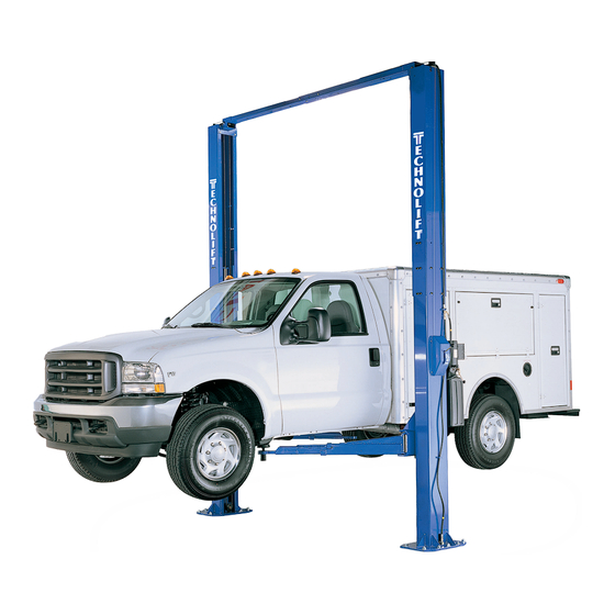
Two Post Surface Mounted Lift
The specifications stated on this brochure are not binding.
We reserve the right to change the specification without notice
ECHNOLIFT
AUTOMOTIVE EQUIPMENT
SL-12
12,000 LBS.
IMPORTANT:
Read this manual completely before
installing or operating lift
Showroom - Distribution Centre
8275, 17e Avenue, Montréal, Qc., Canada H1Z 4J9
1-800-361-4095 • 514-328-2300 • Fax 514-328-4684
Advertisement
Table of Contents

Related Manuals for TECHNOLIFT SL-12


Summary of Contents for TECHNOLIFT SL-12
- Page 1 Two Post Surface Mounted Lift The specifications stated on this brochure are not binding. We reserve the right to change the specification without notice ECHNOLIFT AUTOMOTIVE EQUIPMENT SL-12 12,000 LBS. IMPORTANT: Read this manual completely before installing or operating lift Showroom - Distribution Centre 8275, 17e Avenue, Montréal, Qc., Canada H1Z 4J9...
-
Page 2: General Specifications
SL-12 Installation, Operation and Maintenance ENERAL PECIFICATIONS SL-12 See Figure 1 Rise Height (Screw Pads Highest Position) 78 1/8”" (1984 mm) Overall Height 13’-10" to 14’-7” (4216 mm to 4445 mm) Overall Width 139 3/4" (3550 mm) Drive-Thru Clearance 103" (2616 mm) Floor to Overhead Switch 13’-3 ½"... - Page 3 SL-12 Installation, Operation and Maintenance Safety decals similar to those shown here are ERTICAL LEARANCE found on a properly installed lift. Be sure that all Check the height of the area where the lift is to safety decals have been correctly installed on the be installed.
-
Page 4: Installation
SL-12 Installation, Operation and Maintenance ECEIVING NSTALLATION The shipment should be thoroughly inspected as MPORTANT Always wear safety glasses while installing lift. soon as it is received. The signed bill of lading is OOLS MINIMUM REQUIRED acknowledgement by the carrier of receipt in a. - Page 5 SL-12 Installation, Operation and Maintenance YNCHRONIZER ABLES NCHORING 14) Manually raise each carriage into the second 4) The anchor bolts must be installed at least 8” lock position. from any crack, edge, or expansion joint. 15) At upper beam sheave...
-
Page 6: Final Adjustments
SL-12 Installation, Operation and Maintenance guides as shown and down the backside of the power column. See Fig 7. Fig 5 – Power Unit Mounting Fig 7 – Hose Routing (Power Side) 19) Mount Power Unit to power column as shown 25) Route the remaining Power column hose in Fig 5. - Page 7 SL-12 Installation, Operation and Maintenance Extend the footpad to both extents and apply INAL DJUSTMENTS anti-seize to the three retaining rings and YDRAULICS where the double screw makes contact with 40) Lower the lift to the floor and raise the lift the base of the footpad.
- Page 8 SL-12 Installation, Operation and Maintenance (Normally Open) FIELD CONECTIONS Fig 10 – Electrical Wiring Diagram Page 8...
-
Page 9: Operation Procedure
SL-12 Installation, Operation and Maintenance The Owner/Employer shall display the lift PERATION ROCEDURE manufacturer’s operating instructions; ALI/SM 93 -1, ALI Lifting it Right safety manual; ALI/ST- AFETY OTICES AND ECALS 90 ALI Safety Tips card; ANSI/ALI ALOIM-2000, This product is furnished with graphic safety... -
Page 10: Lifting A Vehicle
SL-12 Installation, Operation and Maintenance IFTING A EHICLE AINTENANCE To avoid personal injury, permit only qualified 1) Insure that the lifting arms are parked, out to personnel to perform maintenance on this full drive thru position. equipment. Maintenance personnel should follow 2) Position the vehicle in the service bay so that lockout/tagout instructions per ANSI Z244.1. -
Page 11: Parts Breakdown
SL-12 Installation, Operation and Maintenance ARTS REAKDOWN ITEM # PART # QTY/LIFT DESCRIPTION JSJ6-02-02-00 POWER COLUMN EXTENSION JSJ6-02-02-00f IDLER COLUMN EXTENSION (NOT SHOWN) JSJ6-03-01-00 OVERHEAD WELD JSJ6-03-02 OVERHEAD SHUT OFF BAR 12045 LIMIT SWITCH X10-060 M10 x 65mm BOLT, POWER COLUMN... - Page 12 SL-12 Installation, Operation and Maintenance ITEM # PART # QTY/LIFT DESCRIPTION JSJ5-02-14A LOCK RELEASE COVER X10-065 M5 x 10 PHILLIPS PAN HEAD SCREW JSJ5-02-12 LOCK RELEASE WIRE PIN JSJ5-02-10 LOCK RELEASE CAM X10-026 M6 x 14mm BOLT JSJ5-02-03 LOCK PAWL...
- Page 13 SL-12 Installation, Operation and Maintenance ITEM # PART # QTY/LIFT DESCRIPTION JSJ6-07-00 HYDRAULIC CYLINDER JSJ6-21 5/8-18 UN 90 DEGREE ELBOW JSJ6-20 5/8-18 UN HOSE EXTENSION (18 ½” LONG) JSJ6-18 5/8-18 UN HOSE (411” LONG) JSJ6-15 9/16-18 UN x 9/16-18 UN x 5/8-18 UN TEE FITTING...
- Page 14 SL-12 Installation, Operation and Maintenance ITEM # PART # QTY/LIFT DESCRIPTION JSJ6-04-00 SYNCHRONIZER CABLE E12-002 HAIRPIN COTTER PIN JSJ6-03-08 CABLE SHEAVE E12-001 26mm WASHER JSJ6-03-03 CABLE SHEAVE PIN JSJ6-03-05 SHEAVE SPACER X10-038 M12 WASHER X10-039 M12 LOCK WASHER X10-053 M12 x 45mm BOLT...
- Page 15 SL-12 Installation, Operation and Maintenance ITEM # PART # QTY/LIFT DESCRIPTION JSJ6-08-00 CARRIAGE X10-085 SLIDE BLOCKS JSJ6-11 ARM PIN JSJ4-05-ch DOOR GUARD X10-087 M8 WASHER X10-088 M8 x 30mm Lg. SOCKET HEAD BOLT X10-077 M10 x 25mm Lg. SOCKET HEAD BOLT...
- Page 16 Two Post Surface Mounted Lift The specifications stated on this brochure are not binding. We reserve the right to change the specification without notice ECHNOLIFT AUTOMOTIVE EQUIPMENT SL-12 12,000 LBS. IMPORTANT: Read this manual completely before installing or operating lift Showroom - Distribution Centre 8275, 17e Avenue, Montréal, Qc., Canada H1Z 4J9...
Need help?
Do you have a question about the SL-12 and is the answer not in the manual?
Questions and answers