Advertisement
Quick Links
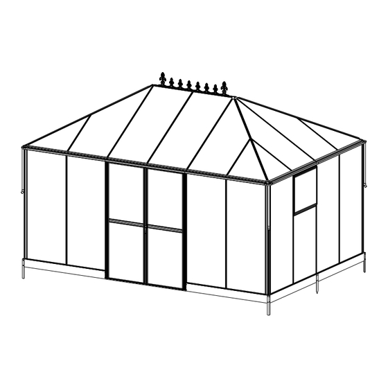
Assembly Instructions
MODEL:AMG604
PRODUCT SIZE(LxWxH):
PLEASE READ CAREFULLY BEFORE ASSEMBLY
Greenhouse 14x10 FT Assembly Instruction
SKU:
1007040043B(BOX 1/4)
1007040044B(BOX 1/5)
1007040045B(BOX 2/4(PC)&3/5(HB))
1007040046B(BOX 3/4(PC)&4/5(HB))
1007040047B(BOX 4/4(PC)&5/5(HB))
1007040048B(BOX 2/5)
Arrive in 4 or 5 separate boxes and may not be part of the same
shipment; Please install the product after receiving all the
packages.
Email Address:cs@howedirect.com
Tel: 901-347-2181
Service Time: 8 am - 5 pm (central time) Monday- Friday.
If no one picks up, please call several more times
14X10
2023/10/20
Advertisement

Related Manuals for Howe AMG604


Summary of Contents for Howe AMG604
- Page 1 Assembly Instructions MODEL:AMG604 PRODUCT SIZE(LxWxH): 14X10 PLEASE READ CAREFULLY BEFORE ASSEMBLY Greenhouse 14x10 FT Assembly Instruction SKU: 1007040043B(BOX 1/4) 1007040044B(BOX 1/5) 1007040045B(BOX 2/4(PC)&3/5(HB)) 1007040046B(BOX 3/4(PC)&4/5(HB)) 1007040047B(BOX 4/4(PC)&5/5(HB)) 1007040048B(BOX 2/5) Arrive in 4 or 5 separate boxes and may not be part of the same shipment;...
- Page 2 CONTENTS 1. Assembly Advice ..............Page 1 2. Product Features ..............Page 2 3. Parts List ................Page 3 -7 4. Door Assembly ..............Page 8 - 11 5. Roof Vent Assembly ............Page 12 - 14 7. Base Assembly ..............Page 15-17 8. Framework & Glazing Assembly ........Page 18 - 36...
- Page 3 CONTENTS 1. Assembly Advice ..............Page 1 2. Product Features ..............Page 2 3. Parts List ................Page 3 -7 4. Door Assembly ..............Page 8 - 11 5. Roof Vent Assembly ............Page 12 - 14 7. Base Assembly ..............Page 15-17 8. Framework & Glazing Assembly ........Page 18 - 36...
- Page 4 Assembly and Maintenance Advice 1. For safety purposes, we strongly recommend that this product is assembled by at least two people. 2. Some components have sharp metal edges. Please be careful when handling metal components. Please wear gloves, shoes and safety goggles during assembly. 3.
- Page 5 Functions and Features: 1. The strong two part eaves beam includes an integral gutter. Downpipes are also included as standard so you can collect rainwater. 2. Manual window handles are included as standard with the roof vents. If required, automatic roof vent openers are available as an inexpensive optional extra. GM80001 Automatic Opener Manual Opener...
- Page 6 PART PART L01A 1678mm L02A A1:1412 B1:1424 1678mm L02B L02C J128 1678mm L02F J148 1570mm L02D 812mm L02E 812mm L03C L03F 1678mm Tools Provided: L05A 1343mm Free Tool L09C L09D 1016mm PART PART PART L03A L15A L03B C1:1392.8 1798mm 649mm D306 L16A L03D...
- Page 7 PART PART PART L06A M6X12 1344mm L07A M5X10 1344mm L07B M5X12 1344mm L08A M4X10 1344mm L08D M6X60 L08E 1344mm L08A D114 L08F A:1344 F:1392 L09A D328 L09B 1356mm L11B L12A 680mm Ø4X16D 680mm M4.2X16 J169 680mm M4.8X16 J171 650mm J174 A100 J175 A101...
- Page 8 PART 801X678mm 801X678mm 1595X678mm 1595X678mm 1598X678mm 1702X678mm 1001X678mm 615X678mm 875X606mm N0.1...
- Page 9 PART 1001X678mm 615X678mm 875X606mm N0.2 PART 801X678mm 801X678mm 1595X678mm N0.3 1595X678mm 1598X678mm 1702X678mm PART J190...
- Page 10 PART Panel Exploded View 801X678mm 801X678mm 1595X678mm 1595X678mm 1598X678mm 1702X678mm 1001X678mm 615X678mm 875X606mm...
- Page 11 PART Left Door L15A L18A L16A Step 1 L16A L18A M5X12 ! Attention: Check the direction of the accessories Step 2 ! Attention:Remove the protective films from both sides of each polycarbonate panel, before inserting into aluminum channels. Ensure the milky white film faces towards the Sun.
- Page 12 L15A L18A L16A L15A S26*2...
-
Page 13: Right Door
PART Right Door L15A L16A L18B L18B Step 1 M5X12 L16A ! Attention: Check the direction of the accessories Step 2 ! Attention:Remove the protective films from both sides of each polycarbonate panel, before inserting into aluminum channels. Ensure the milky white film faces towards the Sun. - Page 14 L15A L15A S26*2...
-
Page 15: Exploded View
PART NO. QTY. Exploded View L11B L12A Ø4X16D M4X10 L12A L11B WindowX2... - Page 16 PART NO. QTY. NO. QTY. Part L11B L12A Ø4X16D M4X10 Step 1 ! Attention:Remove the protective films from both sides of each polycarbonate panel, before inserting into aluminum channels. Ensure the milky white film faces towards the Sun. Step 2...
- Page 17 Step 3 L12A L12A Four windows are standard...
-
Page 18: Base Assembly
PART NO Base Assembly D306 D307 M6X12 D307 D307 Attention! D306 and D307 must be inserted into the soil or installed in reverse!! D306 D306 D306 D306 D306 Fix the base before assembly the greenhouse. This is the way to fix the base. - Page 19 Base Assembly ! Attention:Turn over the steel plinths D306 & D367 & D308 to complete the base installation as shown below, when the greenhouse is NOT inserted and secured into the soft soil. D306 D308 D308 D306 D306 D308 D306...
- Page 20 PART NO Base Assembly D114 M6X60 Fix the base anchor clip D114 onto each base section with a distance of 5~10CM from each end. 2.Mark the middle of the D114 hole to drill the Ø8 hole, then use S69 to fix the D144 to the ground D114 D114 D114...
-
Page 21: Wall Assembly
PART Wall Assembly L01A L01A L03C L03C L05A L01A L08A L05A L08A J169 J174 M5X10 M5X12 L03C S26*3 L08A L08A L08A L03C L05A L05A L08A... - Page 22 PART Wall Assembly L03A L03F L05A L05A L03F L08A L08A L08D L08A L08F L05A D330 L03A L08D J169 L08F M6X12 M5X10 L03C M5X12 L05A L03C L03A L03C S26*3 L08A L05A L08A L05A L08A&L08D L08A&C D330...
- Page 23 PART Wall Assembly L03B L08A L08E D330 L08A L03B J169 J174 M6X12 L08A L08E M5X10 M5X12 L03C L03B L08A D330 L03C S26*3 L08A&L08E L08A L08A L08A L08E...
- Page 24 PART Wall Assembly L01A L03C L05A L03C L01A L01A M5X10 L05A M5X12 L05A L08A L08A L03C L01A L05A L05A L05A L05A...
- Page 25 PART Wall Assembly L02A L02B L02C M5X10 L02A L02A M5X12 L02B L02A L02C L02C L02B L02C Install the L02C air hook close to the end face upwards L02B L02A&L02B&L02C L02A&L02B&L02C Install the L02B with notch closer to the end face upwards L05B...
- Page 26 PART Wall Assembly L07A L07A J171 A100 J175 M5X12 L07A A100 L07A A100 A100 L07A L07A L07A A100 L07A L07A...
- Page 27 PART Wall Assembly L07B L07B J171 M5X12 L07B L07B Connect the end of L07B with a hole on the end face to A98 L07B L07B Before installing L07A, loosen M08 that is fixed to L01A and L05B A100 L07A After installing L07A, replace the removed M08...
- Page 28 PART Wall Assembly M5X10 L07A ! Attention:Remove the protective films from both sides of each polycarbonate panel, before inserting into aluminum channels. Ensure the milky white film faces towards the Sun.
- Page 29 PART Wall Assembly L04A WINDOW M5X10 WINDOW M5X12 L04A L04A L04A L02A S20X4 L04A When installing L04A, the window needs to be lifted up to avoid the window not opening after the installation is complete L11B L07C L07C L02A L02A L11B If the screws for the window installation position have already been installed first It needs to be removed first and replaced with S26...
-
Page 30: Top Assembly
PART Top Assembly L06A J128 J148 J128 M4.2X16 J148 J148 L06A J148 is approximately 80mm from the ends of L06A J128 J148... - Page 31 PART Top Assembly L03D A101 J176 M5X12 L03D The end of L03D with four L03D holes facing upwards L03D L06A L06A S26*3 A101 A101 L03D L03D...
- Page 32 PART Top Assembly L03E M5X12 L03D L03D L03E L03E L03E A101 L03E...
- Page 33 PART Top Assembly D328 M5X10 M5X12 Connect the end of L30 with chamfered downwards to A100 A100 External view Internal view D328 S20*8 M08*8...
- Page 34 PART Top Assembly L02D L02E L02D L02F L02F L02D M5X10 L02E L02E L02D In order to intall L05B effectively later, do not mount screws L02D&L02E in the hole on the sharp angle of L02D L07A L02D L02E L02F L06A L02F L07A L02F...
- Page 35 PART Top Assembly L05B M5X10 L05B M5X12 L05B L05B L05B L05B L03D&E L05B L02D L02E L05B L02F L05B...
- Page 36 PART Top Assembly J178 Ø4X16D J178 ! Attention:Remove the protective films from both sides of each polycarbonate panel, before inserting into aluminum channels. Ensure the milky white film faces towards the Sun.
- Page 37 Top Assembly PART L09A L09B L09E L09D L09A L09C L09B L09C L09E L09D L09B L09C L09E L09A L09D M6X12 M5X12 L09B&C L09D Slide S01 into the bolt channel of both L09B&C, fix D25 to L09B&C using S01 & M01.
-
Page 38: Door Assembly
Door Assembly PART NO D00R-L D00R-R M4.8X16 M5X12 Left Door Right Door Left Door Right Door Fix A51(4 PCS) one side on the door profile and the other side to L26A/L26B using S27. Then secure with Z17. -
Page 39: Accessories Assembly
PART NO Accessories Assembly J177 J177 J177 J177 M4.2X16 Ø4X16D L01A J177 J177 L01A Put J177 on L01A and fix After fixing J177, use glass glue to fill the it on L09A&L09C with Z02. gap between the board and J177. If you wish to eliminate Drill a hole in L01A leaks, use glue when... - Page 40 PART J190 During the installation of endurance boards, it is necessary to install block gine J190 J190 J190 Notice coating the long edge of J190 and endurance boards...
Need help?
Do you have a question about the AMG604 and is the answer not in the manual?
Questions and answers