
Related Manuals for Radio Shack Realistic DX-150


Summary of Contents for Radio Shack Realistic DX-150
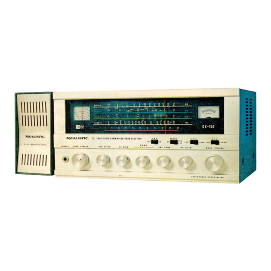
- Page 1 SERVICE MANUAL SOLID STATE FOUR BAND COMMUNICATIONS RECEIVER MODEL DX-150 CAT. 20-150 A PRODUCT OF RADIO SHACK CORPORATION 1 OF 28...
-
Page 2: Table Of Contents
TABLE OF CONTENTS PARAGRAPH TITLE PAGE 1.0 SPECIFICATIONS 2.0 GENERAL ALIGNMENT INSTRUCTIONS 3.0 CHASSIS DIS-ASSEMBLY & DIAL CORD-ASSEMBLY 4.0 WIRING DIAGRAM 5.0 CIRCUIT BOARD DIAGRAM 6.0 CIRCUIT SCHEMATIC DIAGRAM 7.0 PARTS LIST & DESCRIPTION 2 OF 28... -
Page 3: Specifications
SPECIFICATIONS CIRCUIT………………….17 transistors, 13 diodes and 3 thermistors, super- heterodyne system, shown in Table 1 and Fig. 8 Schematic diagram. FREQUENCY……………The R.F. tuning system covers the following four bands: Band A 0.535 – 1.6 MHz Band B 1.55 – 4.5 MHz Band C 4.5 –... - Page 4 TABLE 1. TRANSISTOR & DIODE COMPLEMENT NUMBER TYPE FUNCTION Q1, Q2 2SA234 Cascade R.F. stage 2SA234 Mixer 2SA353 I.F. stage 2SA12 I.F. stage 2SC384 Local Oscillator 2SC371 Oscillator buffer 2SD77 A.V.C. amplifier stage 2SB77 A.V.C. amplifier stage 2SA12 B.F.O. stage 2SA353 B.F.O.
- Page 5 1.11 CONTROLS ON THE FEATURE: TUNING DIAL SPREAD DIAL “S” METER A.N.L. SWITCH (ON / OFF) MODE SWITCH (A.M. / S.S.B., C.W.) A.V.C. SWITCH (FAST / SLOW) OPERATION SWITCH (REC. / STD. BY PHONES JACK BAND SPREAD CONTROL B.F.O. PITCH Power ON / OFF &...
-
Page 6: General Alignment Instructions
GENERAL ALIGNMENT INSTRUCTIONS TEST EQUIPMENT: STANDARD SIGNAL GENERATOR or TEST OSCILLATOR VACUUM TUBE VOLTMETER (P TYPE) (a-c / d-c) or equivalent DUMMY LOAD 8 OHMS I.E.C. DUMMY ANTENNA GENERAL ALIGNMENT CONDITIONS. Before servicing this receiver, disconnect from the power source and remove all lead wires attached to terminal connections. - Page 7 A. S.G. – Coupling. Connect the S.G. output through a capacitor (50 pF) between VC4 and chassis earth. B. S.G. – Frequency………………………….455 KHz. C. Adjust - Adjust the cores of I.F. transformers T1, T2, T3 and T4 for a maximum deflection on the “S” meter in a front dial. R.F.
- Page 8 D. Adjust – Adjust the cores and trimmers of antenna, R.F., and oscillator coils for maximum deflection. Part number of the core and trimmer is as following table: STAGE ANT. STAGE R.F. STAGE OSC. STAGE ADJ. CORE TRIM CORE TRIM CORE TRIM BAND A...
-
Page 9: Chassis Dis-Assembly & Dial Cord-Assembly
CHASSIS DIS-ASSEMBLY & DIAL CORD-ASSEMBLY CHASSIS DIS-ASSEMBLY: See Fig. 2-1 to Fig. 2-3 attached and Item 2.2-1. NOTE: Before the chassis dis-assembly, pull out two of tips with speaker lead from loud speaker. DIAL CORD ASSEMBLY: NOTE: Before the dial cord assembly, seven of all control knobs, five nuts of phone jack, B.F.O. - Page 10 FIG. 1-1 FRONT VIEW OF DX-150 CHASSIS 10 OF 28...
- Page 11 FIG. 1-2 TOP VIEW OF DX-150 CHASSIS 11 OF 28...
- Page 12 FIG. 1-3 BOTTOM VIEW OF DX-150 CHASSIS 12 OF 28...
- Page 13 FIG. 2-1 CHASSIS DIS-ASSEMBLY 13 OF 28...
- Page 14 FIG. FIG. FIG. 14 OF 28...
- Page 15 FIG. 3 MAIN TUNING DIAL CORD ASSEMBLY 15 OF 28...
- Page 16 FIG. 4 BANDSPREAD DIAL CORD ASSEMBLY 16 OF 28...
-
Page 17: Wiring Diagram
WIRING DIAGRAM FIG. 5 DX-150 MAIN CIRCUIT WIRING DIAGRAM (BOTTOM VIEW) 17 OF 28... -
Page 18: Circuit Board Diagram
CIRCUIT BOARD DIAGRAM FIG. 6 DX-150 MAIN CIRCUIT BOARD DIAGRAM 18 OF 28... - Page 19 BOTTOM FIG. 7 DX-150 RF SUB CIRCUIT BOARD & WIRING DIAGRAM (TOP & BOTTOM VIEW) 19 OF 28...
-
Page 20: Circuit Schematic Diagram
CIRCUIT SCHEMATIC DIAGRAM FIG. 8 DX-150 SCHEMATIC DIAGRAM 20 OF 28... -
Page 21: Parts List & Description
PARTS LIST & DESCRIPTION COMMUNICATIONS RECEIVER DX-150 (Cat. No. 20-150) Symbol No. or Item No. Description Rating or Stock No. Remarks Q1, 2, 3 Transistor 2SA234 Q4, Q11 Transistor 2SA353 Q5, Q10 Transistor 2SA12 Transistor 2SC384 Transistor 2SC371 Transistor 2SD77 Q9, Q14 Transistor 2SB77... - Page 22 Symbol No. or Item No. Description Rating or Stock No. Remarks R.F. Choke Coil 10 uH CB-4023 S1, 2, 3, 4, 5, 6, 7, 8 Band Switch Y6124 Out of use Slide Switch 6P 14m / m S11, 12 Slide Switch 6P 14m / m S13, 14 Slide Switch...
- Page 23 Symbol No. or Item No. Description Rating or Stock No. Remarks Electrolytic Capacitor 30uF, 6V (T) Electrolytic Capacitor 2000uF, 15V Block C34, 71, 73, 67 Mylar Capacitor 0.1uF, 25V Mylar Capacitor 0.04uF, 25V Oil Capacitor 0.001uF, 600V C18, 20 Ceramic Capacitor 1pF, +/-10% Ceramic Capacitor 10pF, +/-10%...
- Page 24 Symbol No. or Item No. Description Rating or Stock No. Remarks R1, 9, 12, 14, 20, 21, 30, Resistor 4.7K ohms, ¼ W 46, 59 R2, R3, R8, R11, R15, Resistor 1K ohms, ¼ W R16, R26, R34, R45, R48, R56, R57, R58, Resistor 20K ohms, ¼...
- Page 25 Symbol No. or Item No. Description Rating or Stock No. Remarks Variable Resistor V24N 2kB Variable Resistor V245-SA21 5kA with switch S17, 18 Bonnet GE-11C-552 Chassis GE-11C-521-A Back Plate GE-11C-535-A Bottom Plate Side Angle Plate GE-11C-533-1A &2A Back Cover GE-11C-522-A Dial Back Sub Panel GE-11C-534...
- Page 26 Symbol No. or Item No. Description Rating or Stock No. Remarks Heat Sink Heat Sink Plate GE-11C-534-A “L” Mount Bracket GE-11C-602 for bar antenna “L” Mount Bracket GE-11C-593 for P/C board “L” Mount Bracket GE-11C-538-A for VC “L” Mount Bracket GE-11C-537-A for dial plate Coil Mount Plate...
- Page 27 FIG. 9 TEST EQUIPMENT 27 OF 28...
- Page 28 ANTENNAS An antenna is a necessary adjunct to ALL short-wave receivers. The better the antenna, the more signals you will be able to receive (even weak and remote ones). Because most owners want good results on all short-wave frequencies covered by the DX-150, a suitable antenna for general coverage is sketched above.
Need help?
Do you have a question about the Realistic DX-150 and is the answer not in the manual?
Questions and answers