Advertisement
Quick Links
Advertisement

Related Manuals for JRC NITEC EPS-103


Summary of Contents for JRC NITEC EPS-103
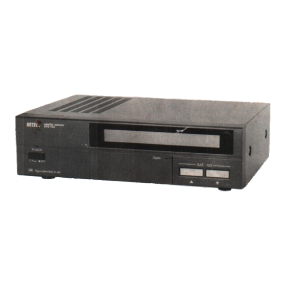
- Page 1 OPERATION MANUAL satellite selector EPS-103...
- Page 2 SAFETY INSTRUCTIONS CAUTION RISK OF ELECTRIC SHOCK DO NOT OPEN CAUTION: TO REDUCE THE RISK OF ELECTRIC SHOCK, DO NOT REMOVE COVER (OR BACK) NO USER-SERVICEABLE PARTS INSIDE REFER SERVICING TO QUALIFIED SERVICE PERSONNEL. The lightning flash with arrowhead symbol, within an equilateral triangle, is intended to alert the user to the presence of uninsulated „dangerous voltage”...
- Page 3 SAFETY INSTRUCTIONS PLEASE READ ALL THESE INSTRUCTIONS AND RETAIN FOR FUTURE REFERENCES. FOLLOW ALL WARNINGS AND INSTRUCTIONS MARKED ON THE UNIT. Read Instructions Grounding or Polarization All the safety and operating instructions should This product is equipped with a 3-wire grounding- be read before the appliance is operated.
- Page 4 SAFETY INSTRUCTIONS (cont’d) Damage requiring Service External Load Unplug this product from the wall outlet and refer Connect the DC motor rated at 24 VDC, 2A servicing to qualified service personnel under the (48W), or less to the product. Operate the pulse following conditions: encoder at the load of 24 VDC, 0.5A (1 2W), or (a) When the power-supply cord or plug is...
-
Page 5: Table Of Contents
satellite selector EPS-103 CONTENTS Page Page GENERAL ......1 - 3 Fine Adjustment SPECIFICATIONS ....2 (TCH MODE) . -
Page 6: General
GENERAL The ROBOT ANTENNA POSITIONER system selected broadcasting satellite is achieved. consists of a satellite selector unit connected to Using advanced electronics technology, in- a parabolic antenna by a Robot Positioner. The cluding state of the art LSI (Large Scale Integra- system allows the user to automatically set the tion) ICs, the ROBOT ANTENNA POSITIONER elevation and azimuth angles of the parabolic... -
Page 7: Specifications
SPECIFICATIONS-FEATURES SPECIFICATIONS Model Name : EPS-103 POWER : 120 VAC, 60Hz. Input Current : 1.5A Control Method : Semi-closed loop, using pulse encoders. Programming : Allows the programming of the azimuth and elevation angles for up to 32 satellites by entering the latitude and longitude of the Robot Positioner installation position. -
Page 8: Functions
FUNCTIONS Front Panel... - Page 9 Rear Panel • Note WHEN using an external cable consisting of 14 wires. COM 2 , 4 , 6 , and 11 are not to be connected. A-phase pulse input terminal for elevation position detec- tion. A-phase pulse input return terminal for elevation position detection.
-
Page 10: Operation
OPERATION -1 Start and Stop Start Press the POWER switch. The POWER indicator (green) lights. Stop Press the POWER switch. The POWER indicator (green) turns off. -2 Selection of Satellite (RUN MODE) Data on the elevation and azimuth angles of 16 satellites is already programmed into the memory. - Page 11 2. Press either the ▲ or ▼ button of the SAT. No. select switches to display the desired satellite number on the LCD. The satellite names in the displayed messages change according to satellite No. ▲ : Counts through the satellite number in ascending order. ▼...
-
Page 12: Fine Adjustment (Tch Mode)
TABLE 1 Satellite Names and Numbers Preprogrammed into the System Memory Satellite Numbers Satellite Name Longitude SAT-2R (SATCOM II R) 72°W GAL-2 (GALAXY II) 74°W COM-3 (COMSTAR III) 76°W SAT-4 (SATCOM IV) 83°W TEL-02 (TELSTAR 302) 86°W WES-3 (WESTAR III) 91°W TEL-01 (TELSTAR 301) - Page 13 3 . Pu sh th e J O G Op e r a ti o n s w i tc h b u tto n o b t a i n e d . T h e e l e v a t i o n a n d a z i m u t h „...
-
Page 14: Programming (Prg Mode)
-4 Programming (PRG MODE): Programming function allows the user to enter direct the antenna to a satellite in such case that values into the system memory to properly data in memory has been lost for any reason. There are four PRG modes: PRG 01 : Enters the latitude and longitude of the antenna’s location. - Page 15 d) Then enter the latitude and longitude in One example of obtaining the LAT/LON in- sequence with the numeric key switches formation is by containing your local FSC (5-digit input). (Flight Service Center). PRG 01 LAT = 034.12N LON = 118.57W e) Push the E switch.
- Page 16 2. Derive the actual home position of the Robot Positioner In the satellite selector, the initial preprogramm- Therefore it is required home position and com- ed home position is: Azimuth = 90° and Eleva- pensate them. tion = 10°. Actually, it may not be sure that the antenna is installed precisely at such angles.
- Page 17 3. Enter the data of actual home position MODE Switch In order to compensate the offset angles, the following operation should be performed. a) Set the MODE switch at „PRG” position. b) Enter „0" and „2" in sequence with the numeric key switches.
- Page 18 4. Indication of azimuth and elevation angles Selection of PRG 03 mode permits display of satellite, as calculated from the latitude and the azimuth and elevation angles of each longitude entered with PRG 01 mode. a) Enter „0" and „3" in sequence with the numeric key switches.
- Page 19 c) The LCD display indicates the azimuth and elevation angles as follows: PRG 03 SAT . 13 *SAT - 3R AZ = 131.0 EL = 027.3 5. Program of new satellites by the user To receive the satellites other than already pro- select PRG04 then program the desired satellite grammed satellites (satellite number 01 ~ 16), at satellite number 17 ~ 31.
- Page 20 c) Enter the satellite number with the numeric switches. PRG 04 SAT.17 LON = • Note To program the new satellite, program the satellite in sequence from satellite number 17. d) Enter the satellite longitude with the numeric switches. PRG 04 SAT.17 LON = 122.00W...
- Page 21 e) Push the E switch. Then the elevation and azimuth of the satellite at the longitude 122.00° is automatically calculated and then programmed. • Note 1) When the calculated elevation and angle of the satellite by enter- ing the satellite longitude is out of elevation range that posi- tioner moves at your position, LCD display indicates the follow- ing message and informs you that the satellite you programmed cannot be seen.
- Page 22 First Printing: April 1985 Second Printing (with corrections): July 1985 Third Printing: September 1985 Fourth Printing (with corrections): January 1986 PRINTED IN JAPAN...
Need help?
Do you have a question about the NITEC EPS-103 and is the answer not in the manual?
Questions and answers