
Subscribe to Our Youtube Channel
Related Manuals for Ledvance LHT-HV-5K F2


Summary of Contents for Ledvance LHT-HV-5K F2
- Page 1 LEDVANCE USER MANUAL HYBRID INVERTER LHT-HV-5K F2 LHT-HV-8K F2 LHT-HV-6K F2 LHT-HV-10K F2 LEDVANCE.COM...
-
Page 2: Table Of Contents
CONTENTS INTRODUCTION PRODUCT DESCRIPTION PRODUCT INSTRUCTIONS PACKAGING SAFETY SAFETY & WARNING GENERAL SAFETY INSTRUCTIONS NOTICE FOR USE NOTICE FOR DISPOSAL OVERVIEW INTELLIGENT LED INDICATORS INSTALLATION MOUNTING THE INVERTER PV INPUT CABLE INSTALLATION BATTERY POWER CABLE INSTALLATION AC CABLE INSTALLATION AC GRID PORT CONNECTION AC BACKUP PORT CONNECTION DISASSEMBLY CONNECTOR COMMUNICATION CABLE INSTALLATION... -
Page 3: Introduction
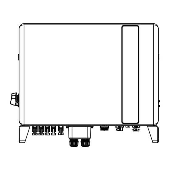
INTRODUCTION PRODUCT DESCRIPTION The LEDVANCE inverters are designed for residential hybrid systems, which can work with batteries to optimize self-consumption. The unit can operate in both off- and on-grid modes. This manual covers the LEDVANCE inverter models listed below: LHT-HV-5K F2, LHT-HV-6K F2, LHT-HV-8K F2, LHT-HV-10K F2... -
Page 4: Product Instructions
PRODUCT INSTRUCTIONS PACKAGING Please ensure that the following items are included in the packaging with your machine: If anything is missing, please contact your local LEDVANCE distributor. Document No.: LDV-LHT-HV-(5-10)K-F2-01-IM_12.2023... -
Page 5: Safety
SAFETY The following types of safety instructions and general information appear in this document as described below: SAFETY & WARNING DANGER “Danger” indicates a hazardous situation which if not avoided, will result in death or serious injury. WARNING “Warning” indicates a hazardous situation which if not avoided, could result in death or serious injury. - Page 6 PV module used with inverter must have an IEC 61730 Class A rating. WARNING Operations below must be accomplished by licensed technician or LEDVANCE authorized person. WARNING Operator must put on the technicians gloves during the whole process in case of any electrical hazards.
-
Page 7: Notice For Use
SAFETY NOTICE FOR USE The inverter has been constructed according to the applicable safety and technical guidelines. Use the inverter in installations that meet the following specifications ONLY: 1. Permanent installation is required. 2. The electrical installation must meet all the applicable regulations and standards. 3. -
Page 8: Overview
OVERVIEW INTELLIGENT LED INDICATORS There are five indicators on the The LEDVANCE inverter (battery, power, wi-fi, ethernet and bluetooth) which indicate the working status of the inverter. The bluetooth antenna or wi-fi datalogger shall be installed at the antenna/COM port of the hybrid inverter before local debugging. -
Page 9: Installation
INSTALLATION SELECT A LOCATION FOR THE INVERTER To select a location for the inverter, the following criteria should be considered: – Exposure to direct sunlight may cause output power derating. It is recommended to avoid installing the inverter in direct sunlight. –... - Page 10 INSTALLATION – Install on a wall or strong structure capable of bearing the weight of the machine (24kg). – Install vertically with a maximum incline of +/- 5 degrees, exceeding this may cause output power derating. – To avoid overheating, always make sure the flow of air around the inverter is not blocked. Minimum clearance of 500mm should be kept between inverters or objects and 1000mm clearance between the bottom of the machine and the ground.
-
Page 11: Mounting The Inverter
INSTALLATION MOUNTING THE INVERTER Dimensions of mounting bracket: unit: mm Inverter wall mounting Once a suitable location has been found, mounting bracket should be mounted to the wall. The inverter must be mounted vertically. The steps to mount the inverter are listed below: 1. - Page 12 INSTALLATION Wall mount bracket WARNING The inverter must be mounted vertically. PE CABLE INSTALLATION An external ground connection is provided at the right side of inverter. Prepare OT terminals: M4. Use proper tooling to crimp the lug to the terminal. Connect the OT terminal with ground cable to the right side of inverter.
-
Page 13: Pv Input Cable Installation
INSTALLATION PV INPUT CABLE INSTALLATION Before connecting inverter, please make sure the PV array open circuit voltage is within the limit of the inverter. Before connection, please make sure the polarity of the output voltage of PV array matches the “DC+” and “DC-” symbols. Please use approved DC cable for PV system. - Page 14 INSTALLATION Positive terminal Negative terminal 4. Connect the wire part of the DC cable to the metal DC terminal and crimp it with a special DC terminal crimping tool. Positive terminal Squeeze Negative terminal 5. Insert the crimped DC cable into the DC terminal firmly, then insert the waterproof rubber ring into the DC terminal and tighten the nut.
- Page 15 INSTALLATION 6. Measure PV voltage of DC input with multimeter, verify DC input cable polarity. 7. Connect the wired DC terminal to the inverter as shown in the figure, and a slight "click" is heard to prove the connection is correct. CLICK CAUTION If DC inputs are accidently reversely connected or inverter is faulty or not...
-
Page 16: Battery Power Cable Installation
INSTALLATION BATTERY POWER CABLE INSTALLATION 1. Take out the two pre-made battery power cables from the package. Cable length: 1 meter. Cross section area is 8mm2. 2. Connect the battery ends to the battery module positive and negative terminals. 3. Measure DC voltage of DC input with multimeter, verify DC input cable polarity. 4. -
Page 17: Ac Cable Installation
INSTALLATION AC CABLE INSTALLATION There are two AC terminals on the inverter and the assembly steps are similar. AC grid port is to connect to the grid and AC backup port is to connect to the critical load circuit. AC-BACKUP terminal AC-BACKUP AC-GRID ANTENNA... - Page 18 INSTALLATION 2. Disassemble the AC grid connector and set the parts on the cable. Body Seal body 3. Crimp wires, screw torque 0.8Nm±0.1Nm. AC Grid 4 . Push housing into body until you hear a “click” sound. Housing CLICK 5. Insert seal body and claw into the body, and then tighten the nut with torque 2.5Nm±0.5Nm. Document No.: LDV-LHT-HV-(5-10)K-F2-01-IM_12.2023...
-
Page 19: Ac Backup Port Connection
INSTALLATION 6. Push the AC backup connector into the AC backup port on the inverter and rotate the rotatory ring on the AC backup connector to the direction as marked “LOCK” on the connector (hold the body while rotating the ring). CLICK NOTE A continuity test shall be made to ensure that the correct terminations have... - Page 20 INSTALLATION Body Seal body 3. Crimp wires, screw torque 0.8Nm±0.1Nm. AC Backup 4 . Push housing into body until you hear a “click” sound. Housing CLICK 5. Insert seal body and claw into the body, and then tighten the nut with torque 2.5Nm±0.5Nm. Document No.: LDV-LHT-HV-(5-10)K-F2-01-IM_12.2023...
-
Page 21: Disassembly Connector
INSTALLATION 6. Push the AC backup connector into the AC backup port on the inverter and rotate the rotatory ring on the AC backup connector to the direction as marked “LOCK” on the connector. (Hold the body while rotating the ring). CLICK NOTE A continuity test shall be made to ensure that the correct terminations have... -
Page 22: Communication Cable Installation
INSTALLATION COMMUNICATION CABLE INSTALLATION PROTECTIVE COVER FOR COMMUNICATION PORTS Inverter in the package is with a protective cover assembled to protect the communication ports. Step 1. Use Phillips screwdriver to take out the 4 screws on the cover. Step 2. Read through the following sections of the manual and prepare the internet cables correspondingly. - Page 23 INSTALLATION COMMUNICATION PORT DEFINITION PORT FUNCTION Used for CAN communication between inverter and lithium battery BMS. Used for RS485 communication between inverter and the smart Meter meter. It is necessary to realize the normal hybrid control logics. (Optional) To realize demand response or logic interface function, this function may be required in UK and Australia.
- Page 24 COMMUNICATION CABLE INSTALLATION (OPTIONAL) FOR REMOTE SHUTDOWN FUNCTION LEDVANCE inverters support remote shutdown function to remotely control the inverter to power on and off through logic signals. The DRM port is provided with an RJ45 terminal and its pin5 and pin6 can be used for remote shutdown function.
- Page 25 INSTALLATION SIGNAL FUNCTION Short pin5 and pin6 Inverter generates Open pin5 and pin6 Inverter shutdown in 5s Correspondence between the cables Rj45 plug and the stitches of plug, pin5 and pin6 of RJ45 terminal is used for the logic interface, other pins are reserved.
-
Page 26: Meter Installation
Strip the insulation layer and connect to RJ45 plug RS485 PORT CONNECTION (OPTIONAL) If a 3rd party external device or controller needs to communicate with the inverter, the RS485 port can be used. Modbus RTU protocol is supported by LEDVANCE inverters. To acquire latest protocol METER INSTALLATION... - Page 27 INSTALLATION NOTE Please note that the CT orientation must be correct, otherwise the system will not work properly. Grid side COMPATIBLE SMART METER MODEL METER RS485 PIN DEFINITION SDM630MCT Pin 13 – RS485B, Pin 14 – RS485A SDM630 B – RS485B, A – RS485A Document No.: LDV-LHT-HV-(5-10)K-F2-01-IM_12.2023...
- Page 28 INSTALLATION Document No.: LDV-LHT-HV-(5-10)K-F2-01-IM_12.2023...
- Page 29 INSTALLATION Document No.: LDV-LHT-HV-(5-10)K-F2-01-IM_12.2023...
-
Page 30: Inverter Remote Monitoring Connection
The USB type COM port at the bottom of the inverter can connect to different kinds of LEDVANCE data loggers to realize the remote monitoring on cloud.ledvance platform. To install LEDVANCE data loggers, please refer to corresponding user manuals of LEDVANCE data loggers. -
Page 31: Commissioning & Shutdown
1. You can visit cloud.ledvance.re to download the latest version APP. 2. You can search “LEDVANCE RE” in Google Play or App Store. 3. You can scan this QR code below to download "LEDVANCE RE". COMMISSIONING PROCEDURE Step 1: Measure DC voltage of PV strings and battery and ensure the polarity is correct. - Page 32 Step 3: Switch on the external AC breaker to power on the inverter control board (bluetooth signal available). Step 4: Connect with bluetooth. Turn on bluetooth switch on your mobile phone and then open the LEDVANCE RE APP. Click “More Tools”->”Local Operation”->”Connect with bluetooth”...
- Page 33 COMMISSIONING & SHUTDOWN Step 7: After the log in for the first time, initial settings are required. Step 7.1: Set the inverter Date and Time. You can set to follow the time on your mobile phone. Step 7.2: Set the battery model. It must be based on the battery model that is actually connected to the inverter.
-
Page 34: Shutdown Procedure
If the Owner forgot the password, please contact the installer. Installer log in and go to “Setting”->”More”->”Change Password” to reset the password for owner’s account. If Installer forgot the password, please contact LEDVANCE service team. SHUTDOWN PROCEDURE Step 1. Turn off the AC breaker at the grid connection point. -
Page 35: Maintenance
MAINTENANCE LEDVANCE inverter does not require any regular maintenance. However, cleaning the heatsink will help inverter dissipating heat and increase the lifetime of inverter. The dirt on the inverter can be cleaned with a soft brush. CAUTION Do not touch the surface when the inverter is operating. Some parts may be hot and cause burns. - Page 36 TROUBLESHOOTING MESSAGE NAME INFORMATION DESCRIPTION TROUBLESHOOTING SUGGESTION Control device to shutdown 1. Turn on the device in the ON/OFF setting. 1. Confirm whether the inverter is connected to an external EPM/meter to prevent reverse current. The device's output is under LmtByEPM 2.
-
Page 37: Troubleshooting
TROUBLESHOOTING MESSAGE NAME INFORMATION DESCRIPTION TROUBLESHOOTING SUGGESTION 1. Grid side fault, restart the device. Surge Alarm On-site grid surge If it is still not eliminated, please contact the manufacturer's customer service. Grid voltage exceeds the upper OV-G-V01 voltage range Grid voltage exceeds the lower UN-G-V01 voltage range Grid frequency exceeds the... - Page 38 TROUBLESHOOTING MESSAGE NAME INFORMATION DESCRIPTION TROUBLESHOOTING SUGGESTION 1. Check on information page 1 – verify the NO-Battery Battery is not connected battery voltage is within standards. 2. Measure battery voltage at plug. 1. Check whether the backup port wiring is normal OV-Vbackup Inverting overvoltage...
- Page 39 TROUBLESHOOTING MESSAGE NAME INFORMATION DESCRIPTION TROUBLESHOOTING SUGGESTION 1. Confirm that the grid is abnormal. OV-G-I 2. Confirm that the AC cable connection is not abnormal. A phase RMS value overcurrent (1018 DATA:0000) 3. Restart the system, confirm that the fault continues.
- Page 40 Please keep ready with you the following information before contacting us. 1. Serial number of LEDVANCE Three Phase Inverter; 2. The distributor/dealer of LEDVANCE Three Phase Inverter (if available); 3. Installation date. 4. The description of the problem together with necessary information, pictures, attachment.
- Page 41 SPECIFICATIONS Technical Data LHT-HV-5K F2 LHT-HV-6K F2 BATTERY Battery Type Li-ion Battery Voltage range 120 - 600Vdc Maximum charging Power Maximum Charge/discharge current Communication CAN/RS485 OUTPUT AC (GRID-SIDE) Rated output power Max. apparent output power 5.5kVA 6.6kVA Rated grid voltage...
-
Page 42: Specifications
SPECIFICATIONS Technical Data LHT-HV-5K F2 LHT-HV-6K F2 OUTPUT AC (BACK-UP) Rated output power Peak apparent output power 8.0kVA, 60 sec 9.6kVA, 60 sec Back-up switch time < 10ms Rated output voltage 3/N/PE, 380V/400V Rated frequency 50 Hz/60 Hz Rated output current 7.6A/7.2A... - Page 43 SPECIFICATIONS Technical Data LHT-HV-5K F2 LHT-HV-6K F2 GENERAL DATA Dimensions(W/H/D) 600*500*230mm Weight 32.6kg Topology Transformerless Self consumption (Night) <25 W Operation temperature range -25°C~+60°C Relative humidity 0-95% Ingress protection IP66 Cooling concept Natural convection Max.operation altitude 4000m G98 or G99, VDE-AR-N 4105 / VDE V 0124, EN 50549-1,...
- Page 44 SPECIFICATIONS Technical Data LHT-HV-8K F2 LHT-HV-10K F2 INPUT DC (PV SIDE) Recommended max. PV power 12800W 16000W Max. input voltage 1000V Rated voltage 600V Start-up voltage 160V MPPT voltage range 200-850V Full load MPPT voltage range 200-850V 250-850V Max. input current 16A/16A/16A/16A Max.
- Page 45 SPECIFICATIONS Technical Data LHT-HV-8K F2 LHT-HV-10K F2 BATTERY AC grid frequency range 45-55 Hz/ 55-65Hz Rating grid output current 12.2A/11.5A 15.2A/14.4A Max. output current 13.4A/12.7A 16.7A/15.8A Power factor >0.99 ( 0.8 leading to 0.8 lagging) THDi <3% INPUT AC (GRID-SIDE) Max.
- Page 46 SPECIFICATIONS Technical Data LHT-HV-8K F2 LHT-HV-10K F2 EFFICIENCY BAT charged by PV Max. efficiency 98.22% 98.31% BAT charged/discharged to AC Max. efficiency 97.50% 97.50% PROTECTION Anti-islanding protection AFCI Insulation resistor detection Residual current monitoring unit Output overcurrent protection Output short protection Output overvoltage protection DC switch DC reverse polarity protection...
- Page 47 SPECIFICATIONS Technical Data LHT-HV-8K F2 LHT-HV-10K F2 GENERAL DATA Ingress protection IP66 Cooling concept Natural convection Max.operation altitude 4000m G98 or G99, VDE-AR-N 4105 / VDE V 0124, EN 50549-1, VDE 0126 / UTE C 15/VFR:2019, RD 1699/RD 244 / Grid connection standard UNE 206006 / UNE 206007-1, CEI 0-21, C10/11, NRS 097-2-1, TOR, EIFS 2018.2, IEC 62116, IEC 61727,...
- Page 48 LEDVANCE GmbH Parkring 29-33 85748 Garching Germany Tel: +48 734 134 386 E-mail: K.rytel@ledvance.com Website: www.ledvance.com Please adhere to the actual products in case of any discrepancies in this user manual. If you encounter any problem on the inverter, please find out the inverter S/N and contact us, we will try to respond to your question ASAP.
Need help?
Do you have a question about the LHT-HV-5K F2 and is the answer not in the manual?
Questions and answers