
Subscribe to Our Youtube Channel
Related Manuals for Ledvance LHS-LV-3K F2


Summary of Contents for Ledvance LHS-LV-3K F2
- Page 1 LEDVANCE USER MANUAL LEDVANCE Single Phase Hybrid Inverter LHS-LV-3K F2 LHS-LV-3.6K F2 LHS-LV-4.6K F2 LHS-LV-5K F2 LHS-LV-6K F2 LEDVANCE.COM...
-
Page 2: Table Of Contents
CONTENTS LEDVANCE HYBRID INVERTER USER MANUAL INTRODUCTION PRODUCT DESCRIPTION PACKAGING SAFETY & WARNING SAFETY GENERAL SAFETY INSTRUCTIONS Notice For Use Notice for Disposal OVERVIEW Intelligent LED Indicators INSTALLATION Select a Location for the Inverter Mounting the Inverter PE Cable Installation... -
Page 3: Introduction
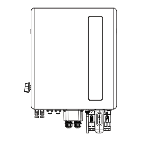
The LHS-LV F2 Series is designed for residential hybrid systems, which can work with batteries to optimize self-consumption. The unit can operate in both off-grid and on-grid modes. This manual covers the LHS-LV F2 Series model listed below: LHS-LV-3K F2, LHS-LV-3.6K F2, LHS-LV-4.6K F2, LHS-LV-5K F2, LHS-LV-6K F2 Front side view... -
Page 4: Packaging
INTRODUCTION PACKAGING Please ensure that the following items are included in the packaging with your machine: If anything is missing, please contact your local LEDVANCE distributor. -
Page 5: Safety & Warning
SAFETY & WARNING SAFETY The following types of safety instructions and general information appear in this document as described below: DANGER: “Danger” indicates a hazardous situation which if not avoided, will result in death or serious injury. WARNING: “Warning” indicates a hazardous situation which if not avoided, could result in death or serious injury. - Page 6 PV module used with inverter must have an lEC 61730 Class A rating. WARNING: Operations below must be accomplished by licensed technician or LEDVANCE auhorized person. WARNING: Operator must put on the technicians' gloves during the whole processin case ofany electrical hazards.
-
Page 7: Notice For Use
SAFETY & WARNING WARNING: The LHS-LV F2 Series does not support parallel in three phase operation on the AC-BACKUP port. The inverter support parallel in single phase and support generator. (Only for 4.6/5/6kW) WARNING: Please refer to the specification of the battery before configuration. Notice For Use The inverter has been constructed according to the applicable safety and technical guidelines. -
Page 8: Overview
OVERVIEW Intelligent LED Indicators There are five indicators on the The LEDVANCE LHS-LV(3-6)K F2 Series Inverter (Battery, Power, WiFi, Ethernet and Bluetooth) which indicate the working status of the inverter. The Bluetooth Antenna or WiFi datalogger shall be installed at the Antenna/COM port of the hybrid inverter before local debugging. -
Page 9: Installation
INSTALLATION Select a Location for the Inverter To select a location for the inverter, the following criteria should be considered: Exposure to direct sunlight may cause output power derating. It is recommended to avoid installing the inver- ter in direct sunlight. It is recommended that the inverter is installed in a cooler ambient which doesn't exceed 104°F/40°C. - Page 10 INSTALLATION – Install on a wall or strong structure capable of bearing the weight of the machine (24.18kg). – Install vertically with a maximum incline of +/- 5 degrees, exceeding this may cause output power derating. – To avoid overheating, always make sure the flow of air around the inverter is not blocked.
-
Page 11: Mounting The Inverter
INSTALLATION Mounting the Inverter Dimenstions of mounting bracket: Inverter wall mounting Once a suitable location has be found accordingly to the figure above and the figure below mount the wall bracket to the wall. The inverter shall be mounted vertically. The steps to mount the inverter are listed below: –... -
Page 12: Pe Cable Installation
INSTALLATION Vertical – Install vertically (+/- 5°) or tilted backward (≤15°). – Don't mount inverter on the tilted forward wall. – Don't mount inverter on the horizontal. PE Cable Installation An external ground connection is provided at the right side of inverter. Prepare OT terminals: M4. Use proper tooling to crimp the lug to the terminal. -
Page 13: Pv Input Cable Installation
INSTALLATION PV Input Cable Installation Before connecting inverter, please make sure the PV array open circuit voltage is within the limit of the inverter. Before connection, please make sure the polarity of the output voltage of PV array matches the“DC+”and“DC-”symbols. Please use approved DC cable for PV system. - Page 14 INSTALLATION – Pass the stripped DC cable through the nut and waterproof rubber ring. Positive Terminal Negative Terminal – Connect the wire part of the DC cable to the metal DC terminal and crimp it with a special DC terminal crim- ping tool.
- Page 15 INSTALLATION –Measure PV voltage of DC input with multimeter, verify DC input cable polarity. –Connect the wired DC terminal to the inverter as shown in the figure, and a slight"click" is heard to prove the connection is correct. CAUTION: If DC inputs are accidently reversely connected or inverter is faulty or not working properly, it is NOT allo- wed to turn off the DC switch.
-
Page 16: Battery Power Cable Installation
INSTALLATION Battery Power Cable Installation NOTE: –The positive wiring (the angle of the limit tip is 90°) is connected to the positive socket, and the negative wiring (the angle of the limit tip is 180°) is connected to the negative socket; –When the terminal is inserted into the corresponding socket, you need to press the circular button on the terminal lightly and pay attention to the direction of the limit pin and the socket slot. -
Page 17: Ac Cable Installation
INSTALLATION AC Cable Installation There are two AC terminals and the assembly steps for both are the same. Take out the AC connector parts from the packaging. Disassemble the AC connector. Strip the AC wires about 9mm. Set the parts on the cable. Crimp wires screw twisting torque 0.8+/-0.1N·m. - Page 18 INSTALLATION Push Housing into Body. Insert Seal and Clamp Finger into socket ,then tighten the nut , torque 4+/-0.5N·m. The same installation for both cable end plug and socket connectors. Mating plug and socket: Push the plug into the socket completely, then rotate the locker according to the direction instructed by the marks on the locker.
-
Page 19: Communication Cable Installation
INSTALLATION Communication Cable Installation Protective Cover for Communication Ports Inverter in the package is with a protective cover assembled to protect the communication ports. Step 1. Use Phillips screwdriver to take out the 4 screws on the cover. Step 2. Read through the following sections of the manual and prepare the internet cables correspondingly. Step 3. -
Page 20: Communication Port Definition
INSTALLATION Communication Port Definition... -
Page 21: Bms Port Connection
INSTALLATION BMS Port Connection Take out the pre-made CAN cable from the package and connect one end to battery CAN port and then con- nect another end to the inverter BMS port. Cable Length: 3 meters. NOTE: Before connecting CAN cable with the battery, please check whether the communication pin sequence of the inverter and the battery match;... -
Page 22: Drm Port Connection (Optional)
DRM Port Connection (Optional) For Remote Shutdown Function LEDVANCE inverters support remote shutdown function to remotely control the inverter to power on and off through logic signals. The DRM port is provided with an RJ45 terminal and its Pin5 and Pin6 can be used for remote shutdown function. - Page 23 If a 3rd party external device or controller needs to communicate with the inverter, the RS485 port can be used. Modbus RTU protocol is supported by LEDVANCE inverters. To acquire latest protocol document, ple- ase contact LEDVANCE local service team or LEDVANCE sales.
-
Page 24: Meter Installation
-One Smart Meter can be used with only one hybrid inverter. The LEDVANCE LHS F2 Series inverter is able to connected Acrel meters or Eastron meters to fuilfill the con- trol logic of the self-consumption mode, export power control, monitoring, etc. -
Page 25: Single Phase Meter Installation
INSTALLATION Single phase meter installation LHS-LV F2... -
Page 26: Inverter Remote Monitoring Connection
The inverter can be remotely monitored via WiFi, LAN or 4G. The USB type COM port at the bottom of the inverter can connect to different kinds of LEDVANCE data log- gers to realize the remote monitoring on LEDVANCE RE platform.To install LEDVANCE data loggers, please refer to corresponding user manuals of LEDVANCE data loggers. -
Page 27: Parallel System Wiring
INSTALLATION Parallel System Wiring NOTE: Only 4.6/5/6kW can be parallel, 3/3.6kW cannot. NOTE: When multiple inverters are connecting in parallel, ONLY same model (same power rating) can be used. -
Page 28: Parallel System Wiring
INSTALLATION Parallel System Wiring NOTE: Only 4.6/5/6kW can be parallel, 3/3.6kW cannot. NOTE: When multiple inverters are connecting in parallel, ONLY same model (same power rating) can be used. -
Page 29: Commissioning
Prepare a multimeter that can do both AC and DC amps. Have an Android or Apple mobile phone with Bluetooth capability. Install the LEDVANCE RE APP on the mobile phone and register a new account. There are three ways to download and install the latest APP. -
Page 30: Operation
OPERATION Power On This inverter can powered by PV only, battery only and Grid only. lt is suggested that turn on the battery firstly, then set the parameters. After setting. turn on PV and GRID breakers to check whether the system runs properly. When the inverter is powered on, the five indicators will be lighted at once. -
Page 31: Log In The App Via Bluetooth
Log in the APP via Bluetooth Step 1: Connect with Bluetooth. Turn on Bluetooth switch on your mobile phone and then open the LEDVANCE RE APP. Click“Tools”->”Local Parameter Setting”->”Bluetooth” Step 2: Select the Bluetooth signal from the inverter. (Bluetooth Name: lnverter SN). - Page 32 OPERATION Initial set up If this is the first time the inverter has been commissioned, you will need to first gothrough the Quick Settings. Once this has been done,these settings can be changed later. Inverter Time -> Battery Model -> Meter Setting ->...
- Page 33 OPERATION C. Meter Setting: Set both the Meter Type and the Meter Location. lt is suggested to install the meter at the system grid connection point and select“Meter in Grid".lf thereis no meter connected for the moment, please select "No Meter" to avoid alarms. D.
- Page 34 OPERATION Self-Use Mode stores the excess PV power into the battery. lf the battery is charged, or there is no battery, the excess PV power will be exported (sold) back to the utility company. lf the system is set to not export any power, then the inverter will curtail the PV power(derate the inverter output power).
- Page 35 OPERATION...
- Page 36 OPERATION APP Interface APP Interface Structure...
- Page 37 OPERATION Home The home page can display the working state, Today Yield of PV, Today lmported/Exported of Grid, Today Charged/Discharged of Battery ,Today Consumption of household electricity and Today GEN yield. At the bottom of page are four submenus: Home, lnfo, Alarm and Settings.
- Page 38 OPERATION Information The lnfo page breaks down into four categories: lnverter, Battery, Grid, and Load. Inverter: inverter power production history, PV voltages and currents, inverter information (serial numbek model number, and firmware version), grid code, and alarm code history.There are two additional information in the inverter page: GEN Information: generator power, today and total generator yield, and warning information.
- Page 39 OPERATION Alarm The alarm page can display the current alarm and the historical alarm. Settings Mode Setting The interface can display the current work mode, Self-Use/Feed in Priority/Off-Grid. Please refer to page xxx for specific introduction. Battery Setting Battery Model: select the battery model to be connected. Peak-shaving setting: lf the switch is enable, the power of force charging will be dynamically adjusted.
- Page 40 OPERATION Force-charge SOC: Due to the battery power consumption, when the over-discharge SOC drops to the force-charge SOC, the inverter will directly charge the battery according to the maximum battery charging current until the battery SOC reaches the over-discharge SOC. (The charging power is nor limited to sources, which may be from PV or from the grid.
- Page 41 OPERATION Meter/CT Setting Meter Type need to be set. lt must be based on the meter type that is actually connected to the inverter. Meter lnstallation Location need to be set. lt is suggested to install the meter at the system grid connection point and select“Meterin Grid”...
- Page 42 OPERATION Grid Power Setting System Export Power/Current: This is the amount of power/current the inverter is permitted to export (or sell ) back to the utility company. lf you do not want the system exporting power, this setting must be configu- red.
- Page 43 OPERATION Generator Setting With Generator: Please turn it on if the generator is ready to work. GEN Power Setting: GEN Rated Power/GEN Max.Charge Power. Generator Position: Grid Port/GEN Port. Grid Port Powered By: lf the generator is connected in Grid Port and the generator works, please select “Generator”.
- Page 44 The inverter commissioning process has now been completed. lt is recommended to monitor the system closely over the next week to ensure that everything is working as it should.Please refer to the LEDVANCE data logger manual for assistance with registering a new plant on LEDVANCE RE.
-
Page 45: Maintenance
MAINTENANCE LEDVANCE S6 Series inverter does not require any regular maintenance. However, cleaning the heatsink will help the inverter dissipate heat and increase the lifetime of inverter. The dirt on the inverter can be cleaned with a soft brush. CAUTION: Do not touch the surface when the inverter is operating. -
Page 46: Troubleshooting
TROUBLESHOOTING... - Page 47 TROUBLESHOOTING...
- Page 48 TROUBLESHOOTING...
- Page 49 TROUBLESHOOTING...
- Page 50 Please keep ready with you the following information before contacting us. Serial number of LEDVANCE Singles Phase Inverter. The distributor/dealer of LEDVANCE Singles Phase Inverter (if available.) Installation date. -The description of the problem together with necessary information, pictures, attachment.
-
Page 51: Specifications
SPECIFICATIONS LHS-LV-3K F2 LHS-LV-3.6K F2... - Page 52 SPECIFICATIONS LHS-LV-3K F2 LHS-LV-3.6K F2...
- Page 53 SPECIFICATIONS LHS-LV-3K F2 LHS-LV-3.6K F2...
- Page 54 SPECIFICATIONS LHS-LV-4.6K F2 LHS-LV-5K F2...
- Page 55 SPECIFICATIONS LHS-LV-4.6 F2 LHS-LV-5K F2...
- Page 56 SPECIFICATIONS LHS-LV-5K F2 LHS-LV-4.6K F2...
- Page 57 SPECIFICATIONS LHS-LV-6K F2...
- Page 58 SPECIFICATIONS LHS-LV-6K F2...
- Page 59 SPECIFICATIONS LHS-LV-6K F2 WIFI communication function needs to use the data logger, LAN communication needs to cooperate with the upper PC. Bluetooth Frequency range:2400-2483.5MHz...
- Page 60 Address: LEDVANCE GmbH, Parkring 1-5 85748 Garching b.München, Germany Contact: Mr. Krzysztof Rytel Mobile: +48 734 134 386 E-mail: k.rytel@LEDVANCE.com Duty: Product Manager LEDVANCE.COM...
Need help?
Do you have a question about the LHS-LV-3K F2 and is the answer not in the manual?
Questions and answers