Table of Contents
Advertisement
Quick Links
Advertisement
Table of Contents

Related Manuals for ABB PVS-120


Summary of Contents for ABB PVS-120
- Page 1 — ABB SOLAR INVERTERS PVS-100/120 medium voltage station Hardware manual...
- Page 3 PVS-100/120 medium voltage station Hardware manual Table of contents 1. Safety instructions 5. Electrical installation 7. Start-up and operation © 2019 ABB Spain. All Rights Reserved. 3AES-PVS-100/120-MVS-00-MA01-A Rev A EFFECTIVE: 2019-05-14...
-
Page 5: Table Of Contents
Table of contents 5 Table of contents 1 Safety instructions Contents of this chapter ................Use of warnings ................... Allowed usage ..................Safe installation, start-up and maintenance ..........General safety instructions ..............MVS working area safety ..............Personal protective equipment (PPE) ..........Safety instructions for MV switchgear and MV transformer area .... - Page 6 6 Table of contents Foundation guidelines ................Placing the MVS on the foundation ............Fastening the MVS ................Constructing earthing electrode and earthing ..........Filling the pit and finalizing the surroundings ..........Adding weather protection hoods .............. Tools ..................... Procedure ..................5 Electrical installation Contents of this chapter ................
- Page 7 Replacing the door limit switch ..............9 Technical data Contents of this chapter ................Technical data and types: PVS-100 MVS ............ Technical data and types: PVS-120 MVCS ........... 10 Drawings Contents of this chapter ................List of technical drawings ................
-
Page 9: Safety Instructions
Safety instructions 9 Safety instructions Contents of this chapter This chapter presents the use of warnings in the manual and gives instructions for safe installation, start-up, use and maintenance of the PVS-100/120 medium voltage station (MVS). Use of warnings Warnings caution you about conditions which can result in serious injury or death and/or damage to the equipment, and advise on how to avoid the danger. -
Page 10: Allowed Usage
ABB technical documents and local regulations. • Make changes to the MVS only with the direct authorization of ABB. Any alterations done outside ABB approval will invalid the warranty for the product. ABB is not liable for any damages caused by these changes. •... -
Page 11: Mvs Working Area Safety
Safety instructions 11 6. Take special precautions when you work close to exposed conductors. 7. Measure to ensure that there is no voltage connected. 8. Carry out earthing (grounding) and short circuiting. 9. Issue a permit to work. ■ MVS working area safety The MVS has three working areas: •... -
Page 12: Safety Instructions For The Auxiliary Services Board
12 Safety instructions e. Turn the disconnecting switch of the MV transformer side of the MV switchgear to open position. Lock and add a warning notice. Disconnect the MV switchgear from the MV network (all possible external power supplies, grid and parallel stations). See the User's manual of the MV switchgear. Lock and add warning notices. -
Page 13: Safe Operation
Safety instructions 13 Safe operation This section contains the safety instructions which you must follow when operating the MVS. If ignored, physical injury or death, or damage may occur. WARNING! Obey these instructions to prevent injury, death, or damage to the equipment WARNING! Keep all doors locked while the MVS is operating. -
Page 15: Hardware Description
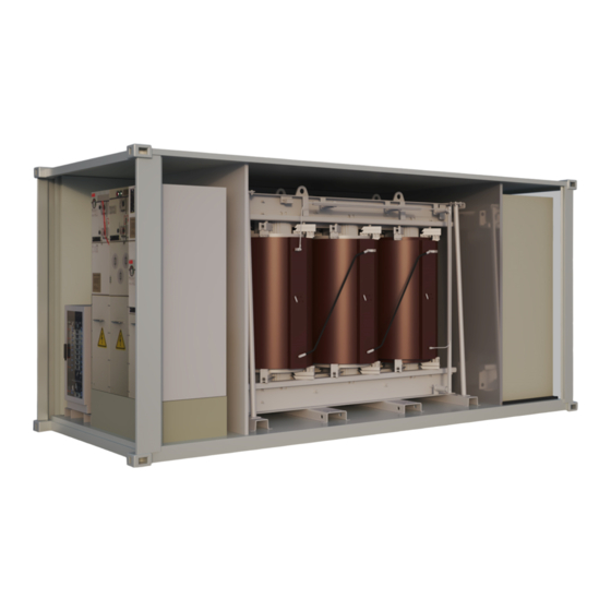
Hardware description 15 Hardware description Contents of this chapter This chapter provides an overview of the PVS-100/120 medium voltage station (MVS). It also includes layout, type designation label and type designation information. Product overview The PVS-100/120 medium voltage station connects a group of inverters to a medium voltage power grid. -
Page 16: Layout Drawing
यां ि त्रक थापना 16 Hardware description थापना साइट की जां च करना Layout drawing ड्राइव को क ै िबने ट म रखा जाना चािहए और दीवार पर थािपत िकया जाना चािहए। R0...R2 This section describes the working areas and main components of the MVS. For more information, see drawing, 3AES-PVS-100_120_MVS-30-DW01. -
Page 17: Main Components
Hardware description 17 • ■ Main components यां ि त्रक थापना नीचे दी गईं आव यकताओं क े अन ु स ार थापना साइट की जाँ च कर: Free area MV switch gear • ड्राइव हािनय को हटाने क े िलए थापना साइट पयार् त प... -
Page 18: Ac Cabinet Components
Main input circuit surge arrester and auxiliary transformer primary feeder protection location Removable back side access panels Description: Medium Voltage Station ■ Inverter inputs Type Designation: Inverter inputs PVS-100-MVCS-... PVS-120-MVCS-... PVS-100/120 - MVS - XXXX- Y – ZZ +options MADE IN SPAIN 1000 1200 MANUFACTURED IN 20XX 1200 1440 1400... -
Page 19: Auxiliary Service Board
Hardware description 19 ■ Auxiliary service board The figure below describes the components of a standard auxiliary service board. Additional components and customization is included in the project specific documentation. See also, UPS connection drawing 3AES-PVS-100/120_MVS-14-SP01. Note: Technical drawings are delivered with the unit, only if you requested. Surge arrester protection for the auxiliary service board Upstream on-load fuse switch for auxiliary service transformer protection Downstream circuit breaker for auxiliary service transformer protection... -
Page 20: Mv Switchgear
20 Hardware description ■ MV switchgear The MVS is always equipped with outdoor MV switchgear. Type CV is used as the standard and consists of two modules: • C uses a double cable bushing configuration to connect to: 1. The grid-side module with grid cable terminals and a disconnecting and earthing switch. -
Page 21: Mv Transformer
Hardware description 21 For more information, see MV switchgear manuals (1YVA000024 and 1YVA000026) ■ MV transformer See MV transformer manual. For dry-type MV transformer, see Operation and maintenance manual (1LES10000-YB). -
Page 22: String Inverter
22 Hardware description ■ String inverter For information on the inverters, see: • String inverter- Product Manual Appendix (9AKK10103A3456) Main circuit diagram The general single-line diagram depends on the configuration and options of the unit as well as the configuration of the inverter group. The table below describes the baseline configurations. -
Page 23: Type Designation Label
Hardware description 23 Type designation label The figure below shows an example of the type designation label. The label contains the पिरवे श ि थितयां • ड्राइव की सं च ालन ि थितयां प ृ ठ पर खं ड म िदए गए िविनदश basic data of the unit. -
Page 24: Type Designation Key
24 Hardware description Type designation key The type designation describes the composition of the unit. The type designation is visible on the type designation label which is attached to the unit. The complete type designation is divided into sub codes: •... - Page 25 Hardware description 25 Code Name Description +MCB Main circuit breaker Addition of a main circuit breaker Station +C5M C5-M corrosion pro- Enclosure and MV transformer standard C4 corrosion protection degree tection degree for is upgraded to enclosure C5M corrosion protection degree. Also, select the upgrade of C5 protection for the dry transformer (+ TRC5).
-
Page 27: Storing, Lifting And Transporting
Storing, lifting and transporting 27 Storing, lifting and transporting Contents of this chapter This chapter provides instructions for storing, lifting and transporting the PVS-100/120 medium voltage station (MVS). WARNING! Inspect carefully the container before performing any activity. Verify that the MVS has no protuberance, lack of rings, or any general poor condition. -
Page 28: Storing
28 Storing, lifting and transporting Storing WARNING! To prevent damage to the MVS, keep the delivery packaging and protection canvas on until you install it. • Always store the MVS in upright position. • Avoid opening the doors unnecessarily and remove the transportation plates during storage and at the time of installation. -
Page 29: Lifting
Storing, lifting and transporting 29 Lifting WARNING! Inspect the container before any activity. Make sure that the container has no protuberance, enough rings and is in good condition. Ignorance of this message can cause physical injury, death or damage to the equipment. Before lifting the MVS, follow these instructions. -
Page 30: Lifting Instructions
30 Storing, lifting and transporting ■ Lifting instructions 1. To lift the station from the top, install the sling vertically and attach it to the upper corner castings. See the locations marked in below figure Top lift spreader configuration 2. To lift the station from bottom, attach the slings from the bottom corner castings to a spreader bar. -
Page 31: Incoming Inspection At Arrival
■ Incoming inspection at arrival • Visually check for any potential transportation damage(s). If any damages found, mark and record them and immediately inform your local ABB representative or your ABB sales contact. • Repair any damaged paint. See section, Maintenance of painted surfaces (page 62). -
Page 33: Mechanical Installation
Mechanical installation 33 Mechanical installation Contents of this chapter This chapter describes the mechanical installation of the PVS-100/120 medium voltage station (MVS) and gives instructions on how to select the location and guidelines to build the foundation for the MVS. Always obey the local regulations. Safety Safety instructions (page Before you move the MVS, see instructions in chapter... -
Page 34: Placing The Mvs On The Foundation
34 Mechanical installation Follow the below guidelines: • To prevent any risk of corrosion, install the MVS higher than its surroundings so that surface water will not collect around its perimeter. • Tilt the surface of the surrounding ground at least 50 mm per meter (two inches per 40 in). -
Page 35: Fastening The Mvs
WARNING! Do not fasten the MVS by electric welding, because the welding circuit can damage electronic circuits and integrity of the station. ABB does not assume any liability for damages caused by electric welding. To fasten the MVS to the foundation, bolt the cabinet through the holes on the base of the inverter or use the supplied attachment brackets (see figure below). -
Page 36: Filling The Pit And Finalizing The Surroundings
36 Mechanical installation Filling the pit and finalizing the surroundings 1. If required for local frost conditions, add insulation around the column foundation. 2. To minimize the growth of grass, use geotextile below the foundation and below the service platform around the MVS. Put the geotextile 20 cm (8 in) below and about 100 cm (40 in) around the foundation. -
Page 37: Adding Weather Protection Hoods
Mechanical installation 37 Adding weather protection hoods ■ Tools • Lifting crane • Working platform or ladder • Automatic screw driver • Wrench • Din933 M6x35 – A2 (Inox) screws • Din9021 M6 – A2 (Inox) + EPDM DIN7712 rubber & metallic washer •... -
Page 38: Procedure
38 Mechanical installation ■ Procedure 1. Unpack the protection hood. 2. Remove the fans transportation plate 3. Apply the sealing product on hood border. - Page 39 Mechanical installation 39 4. Use the lifting crane and place the hood on its frame. 5. Install the washers and screw. For information on torque, see Tightening torque (page 56).
- Page 40 40 Mechanical installation 6. Apply a layer of sealant around the hood border.
-
Page 41: Electrical Installation
Electrical installation 41 Electrical installation Contents of this chapter This chapter contains general instructions for earthing and cabling the PVS-100/120 medium voltage station (MVS). Obey all instructions contained in the applicable documentation (such as other hardware manuals) and the local regulations. WARNING! Only an authorized electrician is allowed to install the cabling to the MVS. -
Page 42: Routing The Cables
Medium Voltage Station Type Designation: PVS-175 - MVS - XXXX- Y +options 42 Electrical installation MADE IN SPAIN Routing the cables MANUFACTURED IN 20XX J When you route the cables: • Install the AC power cables and the control cables on separate routes. •... -
Page 43: Protective Earthing (Grounding) Inside The Mvs
Electrical installation 43 Protective earthing (grounding) inside the MVS The protective earth (PE) terminals or frames of all the main components in the MVS are connected to two main PE busbars located inside the station. At the installation site: • measure the continuity of all internal PE connections by measuring the conductivity between each protective earth terminal and the main PE busbar. -
Page 44: Connecting The Inverter Inputs
Station type Inverter type PVS-100-MVS PVS-100 PVS-120-MVS PVS-120 To connect the inverter inputs, follow the instructions below: 1. Make sure that all cables have the maximum cable size = 185 mm 2. Considering the AC cable sizes and that the cables must be aligned with the fuse bases, mark the LV AC lead through holes in the cable cover: 3. - Page 45 Electrical installation 45 4. Drill holes of appropriate sizes in the AC cabinet cover and install cable glands to ensure that IP protection is established. Individual cabling (single phase) Multicore cabling (3-phase) 5. Route the cables inside the AC cabinet. 6.
-
Page 46: Connecting The Communication And Auxiliary Cabling (Optional)
46 Electrical installation Connecting the communication and auxiliary cabling (Optional) See the following drawings: • Auxiliary cabinet drawing—3AES-PVS-100/120-MVS-14-DW03 • Communication cabinet drawing—3AES-PVS-100/120-MVS-15-SL01 • UPS connection drawing—3AES-PVS-100/120-MVS-16-SP01. To connect the cabling for auxiliary cabinet, communication and UPS: 1. Remove the cable entry covers. 2. - Page 47 Electrical installation 47 4. Fill the cable trenches and seal the cable entries. For more information, see chapter Finalizing the installation (page 49). 5. Connect the cables to correct terminals. Maximum MV cable sizes depend on the connector dimensions. See MV switchgear manual to determine the maximum cable size and configuration (see 1YVA000024 and 1YVA000026).
-
Page 49: Finalizing The Installation
Finalizing the installation 49 Finalizing the installation Contents of this chapter This chapter describes how to finalize and check the installation of the PVS-100/120 medium voltage station (MVS). Obey all local regulations. WARNING! Only an authorized electrician is permitted to install the cabling to the MVS. Obey Safety instructions (page 9), and the local safety regulations. -
Page 50: Landscaping The Station
50 Finalizing the installation Landscaping the station You can plant suitable bushes around the MVS to landscape it. Do not plant trees near the station. If bushes are planted, make sure that the planting compost base is at least two meters away from the MVS, and that the fully- grown bushes will not prevent maintenance access. -
Page 51: Start-Up And Operation
Start-up and operation 51 Start-up and operation Contents of this chapter This chapter describes the start-up procedure of the PVS-100/120 medium voltage station (MVS) and the general operation criteria. WARNING! Only an authorized electrician is permitted to install the cabling to the MVS. Obey Safety instructions (page 9) and the local safety regulations. -
Page 52: Start-Up Procedure
52 Start-up and operation 2. Remove silica gels. See below figure. The locations of silica gels are marked red in color 3. Install the external hood for the fan. See Adding weather protection hoods (page 37). 4. Remove the transportation slings. To access MV transformer area, refer the interlocking drawing that is available with the unit. - Page 53 Start-up and operation 53 Task Additional information Make sure that the main switch of the Auxiliary service transformer is opened. Make sure that all the local regulations, applicable laws, and Contact your local grid and MV standard are met. authority. Turn the earthing switch on the grid side of the MV switchgear Applicable for C module MV to the “not earthed”...
-
Page 55: Maintenance
Maintenance 55 Maintenance Contents of this chapter This chapter contains the preventive maintenance instructions for the PVS-100/120 medium voltage station(MVS). The instructions are intended for certified personnel to perform maintenance tasks. WARNING! Only an authorized electrician is permitted to do maintenance work on the MVS. Obey the Safety instructions (page 9) and follow the local safety regulations. -
Page 56: Tightening Torque
56 Maintenance Tightening torque Use the torque values given in the table, unless otherwise specified. Electrical connections Torque Bolt and nuts Steel: A2-70/A4-70/8.8 (N.m) Brass (N.m) Mechanical connection Torque Bolt and nuts Quality 8.8 A2-70/A4-70 1.21 0.85 2.78 0.80 1.60 2.80 1) Not applicable to threaded inserts... -
Page 57: Maintenance Intervals
The maintenance and component replacement intervals are based on the specified operational and environmental conditions. ABB establishes the following as a minimum maintenance schedule. The MVS final maintenance schedule must be adapted and defined by the maintenance responsible of the plant according to the site conditions, operations and others. -
Page 58: Maintenance Intervals
58 Maintenance Action Task Inspect the temperature and operating conditions of the AC Cabinet using thermography . Examine the grounding system conductivity. This must be done in accordance to local regu- lation and standards. ■ Maintenance intervals Component Years from start-up or interval Cooling fans Air filters R (every six months) - Page 59 Maintenance 59 Task Additional information Use a vacuum cleaner to clean the floor, doors and interior beams. Use a pressurized air to clean the general dust in See MV transformer manual. the MV transformer surface and locations with excessive dust. Use pressurized air to clean locations with excess- ive dust, including busbar connections.
-
Page 60: Replacing Component
60 Maintenance Replacing component 1. Loosen and remove the external screws of the ventilation grille. - Page 61 Maintenance 61 2. Pull the top edge and open the ventilation grille. 3. Pull the air filter frame from the ventilation grille. 4. Remove the plastic clips and the air filter support from the air filter frame. 5. Check and clean the ventilation grille with a vacuum cleaner. 6.
-
Page 62: Maintenance Of Painted Surfaces
Tools and materials Use the following tools and materials. If the listed tools are not available in your local market, you can use products with similar characteristics approved by a qualified technician, and get approval from ABB. Tool Specification Make... -
Page 63: Maintenance Of Zinc Coated Surfaces
Maintenance 63 2. Clean the damaged area and its surroundings using a cloth or blower. 3. If necessary, apply putty to even out the surface. 4. Coat the damaged area with an epoxy primer. Let it dry thoroughly (for at least 24 hours). 5. -
Page 64: Replacing The Door Limit Switch
64 Maintenance 2. After lubricating, clean the excess lubricant. Replacing the door limit switch WARNING! Make sure that the circuit breaker is open and cannot be closed accidently when performing the task. 1. Open the main circuit breaker of the auxiliary panel. 2. -
Page 65: Technical Data
Technical data 65 Technical data Contents of this chapter This chapter contains the technical data of the PVS-100/120 medium voltage station (MVS). -
Page 66: Technical Data And Types: Pvs-100 Mvs
Protection (up to 24 kV / up Circuit breaker (16 kA or 20 kA / 20 kA or 25 kA) to 36 kV) Protection relay type ABB REJ603 (others on request) Motorized optional Auxiliary supply Auxiliary transformer power 10 kVA (higher on request) - Page 67 Technical data 67 Type code (PVS-100-TL-... Data 1000 1200 1400 1600 1800 2000 2200 2400 2600 Relative humidity ≤ 95% (non-condensing) Environmental protection IP 54 rating Painting corrosion protection C4 (C5M optimal) Product compliance Conformity IEC 60364, IEC 61936-1, IEC 60502-1...
-
Page 68: Technical Data And Types: Pvs-120 Mvcs
68 Technical data Technical data and types: PVS-120 MVCS Type code (PVS-120-TL-... Data 1200 1440 1680 1920 2160 2400 2640 2880 3120 Number of inverters in parallel Maximum rating in kVA 1200 1440 1680 1920 2160 2400 2640 2880 3120... - Page 69 Technical data 69 Type code (PVS-120-TL-... Data 1200 1440 1680 1920 2160 2400 2640 2880 3120 Relative humidity ≤ 95% (non-condensing) Environmental protection IP 54 rating Painting corrosion protection C4 (C5M optimal) Product compliance Conformity IEC 60364, IEC 61936-1, IEC 60502-1...
-
Page 71: Drawings
Drawings 71 Drawings Contents of this chapter This chapter contains the technical drawings of PVS-100/120 medium voltage station (MVS). List of technical drawings The list includes two types of drawings: • Product Series—Standard product series drawings that can be consulted prior to the purchase of the unit. -
Page 73: Further Information
Product and service inquiries Address any inquiries about the product to your local ABB representative, quoting the type designation and serial number of the unit in question. A listing of ABB sales, support and service contacts can be found by navigating to new.abb.com/power-converters-inverters/solar. - Page 74 3AES-PVS-100/120-MVS-00-MA01-AA © 2019 ABB Spain. All Rights Reserved. Specifications subject to change without notice.
Need help?
Do you have a question about the PVS-120 and is the answer not in the manual?
Questions and answers