Advertisement
Quick Links
INSTALLATION GUIDE
ASCDIM/DALI/4IN1
Product Installation Guide
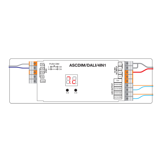
DALI Loop-In And
Digital Display
Loop-Out Terminals
Digital Display Controls
Product Information
Input
Output
Output
Remarks
Voltage
Current
Power
Constant
12-36VDC
4x5A
4x (60-180)W
voltage
Dimensions
12-36V DC Power Input
Common Anode Output (+)
R/WW/DIM Output (-)
G/CW/DIM Output (-)
B/WW/DIM Output (-)
W/CW/DIM Output (-)
DALI
Dimming
Size (LxWxH)
Consumption
Range
170x53.4x28mm
2mA
0.1%-100%
170mm
!
Operation
1. Select a DALI Device Type
PLEASE READ
1.1. Press and hold down both buttons until digital display flashes, then release the button.
BEFORE USE!
1.2. Keep clicking the 2nd button, you will get the 8 device types one by one as follows, 6 of them are
valid modes, please ignore the other 2 modes which are invalid here:
means 2 Tc colour type devices integrated in one control gear, which can control 2 groups of tunable
white LED separately using 2 DALI addresses under this mode.
(invalid mode since this mode requires 5 PWM channels), means XY & Tc colour type devices
integrated in one control gear, which can control RGB & CCT LED separately using 2 DALI addresses under this mode.
(invalid mode since this mode requires 5 PWM channels), means RGBWAF & Tc colour type devices integrated in
one control gear, which can control RGB & CCT LED separately using 2 DALI addresses under this mode.
, means XY & DT6 type devices integrated in one control gear, which can control RGB & W LED separately using 2 DALI
addresses under this mode.
, means XY coordinate colour type, which can control RGB LED using 1 DALI address under this mode.
, means Tc colour type, which can control tunable white LED using 1 DALI address under this mode.
, means RGBWAF colour type, the device can control RGBW LED using 1 DALI address under this mode.
, means DT6 device type, which can control single colour LED using 1 DALI address under this mode.
1.3. Select a device type you would like and then press and hold down both buttons until digital display stops
flashing to confirm the selection.
2. Setting a DALI Address
This device by default is set to no DALI address. To set the address up please read below. Available DALI Addresses are 00-63.
Press and hold down the right hand button until the digital display flashes, then release.
2.1. By pressing the buttons, scroll through the numbers until the desired address has been set.
2.2. Press and hold down the right button until the digital display stops flashing to save the settings.
Note: DALI address can be manually assigned from 00-63. The factory default setting is that no DALI address is
assigned to the unit. To Factory reset the device select
Note: Should a DALI master be used to set the address on the controllers, the digital display will read
Ambient
Temperature
-20°C ~ +50°C
3. Push Dimming Mode
While connected with an AC push switch, the digital display will show
under Push Dimmer Mode are as follows:
While
device type is selected, only the 1st group tunable white LED will be controlled by the push switch,
• Click the button to switch ON/OFF
• Press and hold down the button to increase or decrease light intensity to desired level and release it, then repeat the
operation to adjust light intensity to opposite direction. The dimming range is from 1% to 100%.
• Double click the button to switch between brightness mode and colour temperature mode.
• Press and hold down the button to change colour temperature under colour temperature mode.
While
device type is selected, only the RGB LED will be controlled by the push switch,
• Click the button to switch ON/OFF
• Press and hold down the button to increase or decrease light intensity to desired level and release it, then repeat the
operation to adjust light intensity to opposite direction. The dimming range is from 1% to 100%.
• Double click the button to switch between brightness mode and RGB colour mode.
• Press and hold down the button to change RGB colours under RGB colour mode.
on the digital display.
which means Push Dimmer Mode, operations
Advertisement

Related Manuals for All LED ASCDIM/DALI/4IN1


Summary of Contents for All LED ASCDIM/DALI/4IN1
- Page 1 2 Tc colour type devices integrated in one control gear, which can control 2 groups of tunable white LED separately using 2 DALI addresses under this mode. ASCDIM/DALI/4IN1 (invalid mode since this mode requires 5 PWM channels), means XY & Tc colour type devices Product Installation Guide integrated in one control gear, which can control RGB &...
- Page 2 1.1.2 When total load of each receiver is over 10A While device type is selected, RGB LED will be controlled by the push switch, • Click the button to switch ON/OFF • Press and hold down the button to increase or decrease light intensity to desired level and release it, then repeat the operation to adjust light intensity to opposite direction.
- Page 3 1.4.2 When total load of each receiver is not over 10A 1.3 When single-address XY device type selected 1.3.1 When total load of each receiver is not over 10A Note: 1) Please make sure that the DALI master controller supports Tc colour type commands. 2) 2 groups CCT LED are controlled together.
- Page 4 2.1.1 Retractive/Push Dimming Wiring Diagrams 1.5.2 When total load of each receiver is over 10A 2.1 When multi-addresses Tc device type selected 2.1.1 When total load of each receiver is not over 10A RETRACTIVE SWITCH Note: Please make sure that the DALI master controller supports RGBWAF colour type commands. 2.1.2 1.6 When single-address DT6 device type selected...
- Page 5 2.4.2 2.2.2 When total load of each receiver is over 10A 2.4.2 When total load of each receiver is not over 10A RETRACTIVE SWITCH RETRACTIVE SWITCH Note: only the RGB LED can be controlled under this mode. 2.3 When single-address XY device type selected 2.3.1 When total load of each receiver is not over 10A 2.5.1 Note: 2 groups CCT LED are controlled together under this mode.
- Page 6 • All installations must be carried out in accordance with this installation guide and user manual. • All goods are supplied under the terms and conditions of ALL LED LTD, a copy of which may be obtained upon written request.
Need help?
Do you have a question about the ASCDIM/DALI/4IN1 and is the answer not in the manual?
Questions and answers