Table of Contents
Advertisement
Available languages
Available languages
Quick Links
Advertisement
Table of Contents

Subscribe to Our Youtube Channel
Related Manuals for WAVEFIT B300 Surge Series


Summary of Contents for WAVEFIT B300 Surge Series
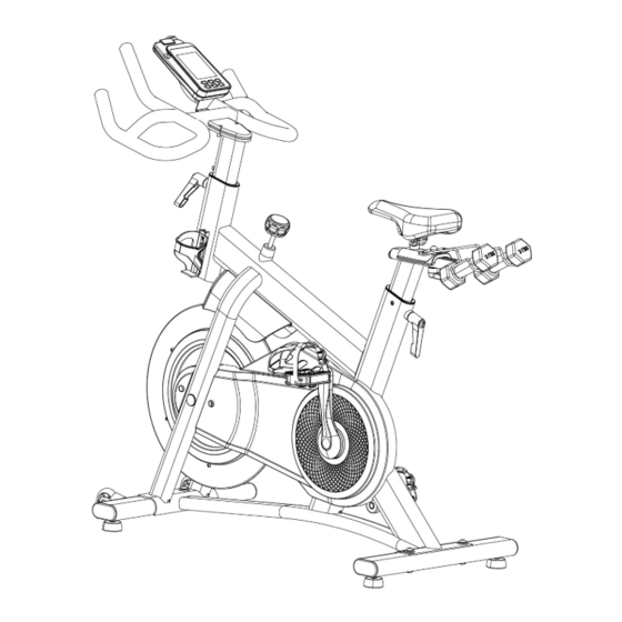
- Page 1 Owner’s Manual Surge Series B300 Bluetooth Connected Indoor Cycle...
-
Page 2: Table Of Contents
Table of Contents Table of Contents Safety Instruction (general) ………………………………………………………………….………………. Safety Instructions (usage) ………………………………………………………………….………………. Safety Instructions (assembly) ………………………………………………………………….………………. Warnings ………………………………………………………………….………………. Hardware and Parts List ………………………………………………………………….………………. Assembly Instructions ………………………………………………………………….………………. Specifications ………………………………………………………………….………………. Warranty ………………………………………………………………….………………. Registration ………………………………………………………………….………………. Tabla de contenido Instrucciones de Seguridad: (Generales) …………………………………………………………………….. -
Page 3: Safety Instruction (General)
Safety Instructions SAFETY INSTRUCTIONS: (General) We thank you for choosing our product. To ensure your safety and health it is important to read this entire manual before assembling and using the equipment. Safe and productive use can only be achieved if the equipment is assembled, maintained and used properly. It is your responsibility to ensure that all users of the equipment are informed of all warnings and precautions. -
Page 4: Safety Instructions (Assembly)
Safety Instructions SAFETY INSTRUCTIONS: (Usage) Always use the equipment as indicated. If you find any defective components while assembling or checking the equipment, or if you hear any unusual noises coming from the equipment during exercise, discontinue use of the equipment immediately and do not use until the problem has been rectified. - Page 5 Do not try to change the design or functionality of this machine. This could compromise the safety of this machine and will void the warranty. If replacement parts are necessary use only genuine replacement parts and hardware supplied by WaveFit. Failure to use genuine replacement parts can cause a risk to users, keep the machine from operating correctly and void the warranty.
-
Page 6: Warnings
Warnings WARNINGS: To reduce the risk of burns, fire, electric shock, or injury to persons: 1. Use this appliance only for its intended use as described in this manual. 2. Do not use attachments not recommended by the manufacturer. 3. Keep away from heated surfaces. 4. -
Page 7: Hardware And Parts List
Hardware and Parts List Hardware List Exploded drawing Part No. Description Screw, M8 x P1.25 x 56L Screw, M8 x P1.25 x 25L Screw, M5 Nut, M8 Spring Washer, dia. 8.1 x 14.5 x 2.4T Flat Washer, dia. 8 x dia. 19 x 2T Open Wrench, VM230, 13.15 x 5T Wrench, hexagon, 6mm Part List... -
Page 8: Assembly Instructions
Assembly Instructions STEP 1 - Attach Stabilizers Attach Front Stabilizer - Identify Front Stabilizer (86) and position it under the Mainframe (62) as shown. Attach the front stabilizer to the frame using the hex wrench (83) with two M8 bolts (44), two M8 spring washers (94), and two M8 flat washers (3). - Page 9 Assembly Instructions STEP 2 - Attach Pedals Attach Right Pedal - Identify the Right pedal (36). Using your fingers, slowly turn the right pedal about halfway onto the Right crank arm. Then, use the wrench (97) to fully tighten the right pedal to the right crank. Attach Left Pedal - Identify the Left pedal (53).
- Page 10 Assembly Instructions STEP 2b - Attach Handlebar Post Attach Handlebar Post - Identify the Handlebar Post (8) and Adjustment Pin (29). Remove the Adjustment pin. Insert Handlebar Post into the Mainframe as shown. Adjust to desired height and replace the adjustment pin. STEP 2c - Attach Seat Post Attach Seat Post - Identify the Seat Post (28) and Adjustment Pin (29).
- Page 11 Assembly Instructions STEP 3 - Attach Handlebars Secure Handlebars to Handlebar Post - Identify the, Handlebars (2), Handlebar Post (8), M8 Bolt (7), M8 flat washer (3) M8 spring washer (94), and M8 nut (4). Identify the following tools, hex wrench (83) and open wrench (97). Place the Handlebars on the Handlebar Post.
- Page 12 Assembly Instructions STEP 4 - Attach Seat Identify Seat (23) and Seat Post (28). Remove seat height adjustment knob on mainframe. Slide the Seat Post (28) down into the mainframe of the equipment. Tighten the seat height adjustment knob to secure the seat post. This knob is used to adjust seat height.
-
Page 13: Specifications
Specifications SPECIFICATIONS FCC INFORMATION Maximum User Weight: 125 kg (275 lbs.) Dimensions: 101.6 x 50.8 x 115.6 cm This equipment has been tested and found to comply with the limits for a (L 40 x W 20 x H 45.5 in.) Class B digital device, pursuant to part 15 of the FCC Rules. -
Page 14: Warranty
This warranty extends only to the original purchaser (customer) and is not transferable. WaveFit’s obligation under this warranty is limited to repairing or replacing, at WaveFit’s discretion, the product through one of its authorized service providers. All repairs for which warranty claims are made must be pre-authorized by WaveFit. If replacement parts are shipped while the product is under warranty, the customer may be responsible for a minimal handling charge. - Page 15 El manual del propietario Surge Series B300 Bicicleta para uso Interior con conexión Bluetooth...
-
Page 16: Instrucciones De Seguridad: (Generales)
Las instrucciones de seguridad INSTRUCCIONES DE SEGURIDAD: (Generales) Le agradecemos que haya elegido nuestro producto. Para garantizar su seguridad y salud, es importante leer este manual en su totalidad antes de ensamblar y utilizar el equipo. El uso seguro y productivo solo se puede lograr si el equipo se ensambla, mantiene y usa correctamente. -
Page 17: Instrucciones De Seguridad: (Uso)
Las instrucciones de seguridad INSTRUCCIONES DE SEGURIDAD: (Uso) Utilice siempre el equipo como se indica. Si encuentra algún componente defectuoso mientras ensambla o revisa el equipo, o si escucha ruidos extraños provenientes del equipo durante el ejercicio, deje de usar el equipo inmediatamente y no lo use hasta que se haya solucionado el problema. -
Page 18: Instrucciones De Seguridad: (Montaje)
Si es necesario reemplazar piezas, use solo piezas de repuesto y hardware originales suministrados por WaveFit. La falta de uso de piezas de repuesto originales puede causar un riesgo para los usuarios, impedir que la máquina funcione correctamente y anular la garantía. -
Page 19: Advertencias
Advertencias ADVERTENCIAS: Para reducir el riesgo de quemaduras, incendios, descargas eléctricas o heridas personales: 1. Use este aparato solo para el uso pretendido como esta descrito en este manual. 2. No utilice accesorios no recomendados por el fabricante. 3. Manténgase alejado de superficies calientes. 4. -
Page 20: Lista De Hardware Y Piezas
Lista de hardware y piezas Lista de hardware Dibujo ampliado Parte № Descripción ctdad Pernos, M8 x P1.25 x 56L Pernos, M8 x P1.25 x 25L Pernos, M5 Tuerca, M8 Arandela de resorte, dia. 8.1 x 14.5 x 2.4T Arandela planas, dia. 8 x dia. 19 x 2T llave inglesa, VM230, 13.15 x 5T Llave hexagonal, 6mm Lista de piezas... -
Page 21: Instrucciones De Montaje
Instrucciones de montaje PASO 1 - Fije los estabilizadores Conecte el estabilizador delantero - Identifique el Estabilizador Delantero (86) y colóquelo debajo de la Estructura Principal (62) como se muestra. Fije el estabilizador delantero al bastidor con la llave hexagonal (83) con dos pernos M8 (44), dos arandelas elásticas M8 (94) y dos arandelas planas M8 (3). - Page 22 Instrucciones de montaje PASO 2 - Acople los pedales Acople el pedal derecho - Identifique el pedal Derecho (36). Con los dedos, gire lentamente el pedal derecho hasta la mitad del brazo derecho de la biela. Luego, use la llave (97) para apretar completamente el pedal derecho a la biela derecha.
- Page 23 Instrucciones de montaje PASO 2b - Acople el poste del manubrio Fijación del poste del manubrio Identifique el Poste del manubrio (8) y el perno de ajuste (29). Retire el perno de ajuste. Inserte el poste del manubrio en la estructura principal como se muestra.
- Page 24 Instrucciones de montaje PASO 3 - Acople los manillares Asegure los manillares as poste del manubrio Identifique los manillares (2), el poste del manubrio (8), el perno M8 (7), la arandela plana M8 (3) y la tuerca M8 (4). Identifique las siguientes herramientas, llave hexagonal (83) y llave abierta (97).
- Page 25 Instrucciones de montaje PASO 4: Adjunte el asiento Identifique el Asiento (23) y el Poste del Asiento (28). Retire la perilla de ajuste de altura del asiento en la estructura principal. Deslice el Poste del Asiento (28) hacia abajo dentro de la estructura principal del equipo.
-
Page 26: Especificaciones
Especificaciones Especificaciones INFORMACIÓN DE LA FCC Peso máximo del usuario : 125 kg (275 lbs.) Dimensiones: 101.6 x 50.8 x 115.6 cm Este equipo ha sido probado y establecido que cumple con los límites para un (L 40 x W 20 x H 45.5 in.) aparato digital de Clase B, de conformidad segun la parte 15 de las Reglas de la peso neto: 47.7 Kg (105.2 lb) FCC. -
Page 27: Garantía
Esta garantía proporciona derechos legales específicos; el cliente puede tener otros derechos que varían de un estado a otro. Para el servicio de garantía, por favor visite www.wavefit.net y siga las instrucciones para presentar un reclamo de garantía. Por favor tenga a mano el número de modelo y el número de serie del producto. -
Page 28: Registración Del Producto
How to assembly videos Registering your fitness equipment is important to ensuring your These videos show you how to assemble your WaveFit equipment’s warranty. By activating your warranty you will expedite the product using the tools, hardware parts, and user manual service of your equipment should it need any maintenance or repairs.
Need help?
Do you have a question about the B300 Surge Series and is the answer not in the manual?
Questions and answers