Table of Contents
Advertisement
Quick Links
Advertisement
Table of Contents
Troubleshooting

Related Manuals for Dyaco XS895


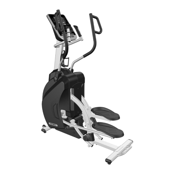
Summary of Contents for Dyaco XS895
- Page 1 XS300B- YS006 Service Manual Service Manual...
-
Page 2: Table Of Contents
6-1-4 THE CONSOLE INTERFACE BOARD WIRE CONNECTIONS ........................21 6-1-5 AMPLIFIER BOARD WIRE CONNECTIONS ............................22 6-1-6 TENSION MOTOR CONNECTOR DEFINITION FUNCTION ........................23 7. Error Messages /Troubleshooting ..................................24 7-1 Error Codes ........................................ 25 7-2 Prepare tools ......................................25 Dyaco International Inc. - Page 3 10-7 Rear Rail Assembly replacement ................................54 10-8 Incline motor, Gear motor, and Controller board replacement ........................ 55 10-9 Idler Wheel Assembly, Flywheel, and Drive belt replacement ........................57 10-9 Crank and Drive pulley replacement ................................ 58 Dyaco International Inc.
-
Page 4: Outlines
1. Outlines Dyaco International Inc. -
Page 5: Electronic Parts
2. Electronic Parts Dyaco International Inc. -
Page 6: Upper Controllers
2-1 Upper Controllers Display Dyaco International Inc. -
Page 7: Lower Controller And Driver
2-2 Lower Controller and Driver Tension Motor Incline motor Speed Sensor Dyaco International Inc. -
Page 8: Electrical Configurations
3. Electrical Configurations Dyaco International Inc. - Page 9 If there is AC voltage on the Red wire (UP) the incline motor will increase the incline. If there is AC voltage on the Black wire (DOWN) the incline motor will decrease the incline. The White wire (COM) is neutral. The green wire is ground. Dyaco International Inc.
-
Page 10: Product Operation
4. Product Operation Dyaco International Inc. -
Page 11: Display Windows
4-1 Display Windows 7.5” LCD Display Dyaco International Inc. -
Page 12: Operation
Pulse value displays anytime the upper display is receiving a Pulse signal. You may not use the Pulse Grip feature while in Heart Rate Programs. 4-2-5 Calorie Display Dyaco International Inc. -
Page 13: Speakers
Stop key performs previous screen or segment function. This allows you to go back to change programming data. 4-2-9 Program Keys The program keys are used to preview each program. When you first turn the console on you may press each program key to preview what the program profile Dyaco International Inc. - Page 14 % in relation to your projected maximum heart rate, which is determined by your age that you entered during the programming phase of any of the 10 programs. The significance of the bar graph colors are as follows: 50-60% of maximum is Amber 65-80% of maximum is Amber and Green 85-90% or more is Amber, Green, and Red Dyaco International Inc.
-
Page 15: Function Button Locations
4-3 Function Button Locations PROGRAM BUTTONS (Manual, Hill, Fat Burn, Cardio, Strength, Control Keys HIIT, 2User, 2HR) FAN KEY Cooling fan switch on or off Dyaco International Inc. -
Page 16: Unit Block Diagrams
5. Unit Block Diagrams Dyaco International Inc. - Page 17 Dyaco International Inc.
-
Page 18: Basic Connections And Wiring
6. Basic Connections and Wiring Dyaco International Inc. -
Page 19: Display Board Pcb Component Locations
6-1 Display Board PCB Component Locations 6-1-1 DISPLAY BOARD WIRE CONNECTIONS Dyaco International Inc. -
Page 20: Pcb Board Top
6-1-2 PCB BOARD TOP Dyaco International Inc. -
Page 21: Pcb Board Bottom
6-1-3 PCB BOARD BOTTOM Dyaco International Inc. -
Page 22: The Console Interface Board Wire Connections
6-1-4 THE CONSOLE INTERFACE BOARD WIRE CONNECTIONS Dyaco International Inc. -
Page 23: Amplifier Board Wire Connections
6-1-5 AMPLIFIER BOARD WIRE CONNECTIONS Dyaco International Inc. -
Page 24: Tension Motor Connector Definition Function
6-1-6 TENSION MOTOR CONNECTOR DEFINITION FUNCTION STEEL ROPE SPEED SENSOR 1 GND 2 SPEED Dyaco International Inc. -
Page 25: Error Messages /Troubleshooting
7. Error Messages / Troubleshooting Dyaco International Inc. -
Page 26: Error Codes
7-1 Error Codes Error Code CAUSE EEPROM is defective or operate abnormal. Tension motor is failure Incline motor error 7-2 Prepare tools Multi-meter Dyaco International Inc. -
Page 27: Error Message:e1
Troubleshooting The display board requires replacement. 7-4 Error Message:E2 Definition Gear motor operate abnormal or display board can’t receive signal from gear motor. Troubleshooting 1. Check the control cable and replug it. 2. Check the tension motor. Dyaco International Inc. - Page 28 Dyaco International Inc.
-
Page 29: Tension Motor Operation
Inspect drive board power output to the motor. Press the Level Up is +5VDC;Level DOWN is -5VDC.If there is power to the motor, but the motor does not operate, replace it. If there is no power output, inspect whether the drive board has power. Dyaco International Inc. -
Page 30: Tension Motor Voltage Test Procedure
If there is no voltage,inspect power socket the holder FUSE.If broke replace it. Inspect the drive board POWER LED whether lit.If no lit the drive board is bad.Replace it. Place probes on the motor control wire(Red probe in blue wire, Black probe in green wire) on the drive board. Dyaco International Inc. -
Page 31: Error Message:e3
7-5 Error Message:E3 Definition The console board is not detecting the VR voltage value or the voltage value has exceeded the range.” STEP ERROR” appears on the display. Configuration Dyaco International Inc. - Page 32 Incline motor isn’t operation up or down, making the VR value exceed the range. After turning on the unit, the display board detects that the incline VR voltage exceeds the range, so INCLINE E3 appears. Action Flow Chart Dyaco International Inc.
- Page 33 2. Test whether the VR voltage varies at the incline wire Stepper. 11-pin cable 1. Inspect the wire connections. 2. Inspect whether wires are broken or crimped. 3. Replace the wires and test again. Driver board Inspect the display board 11-pin connections. Dyaco International Inc.
-
Page 34: Test Configuration. The Console To Driver Board Connector Pin Define Function
7-6 Test configuration. The console to driver board connector pin define function HR HAND POWER 1.SPEED 2.GND 3.VCC+5V 4.ZERO 5.COUNT 6.MOTOR- 7.MOTOR+ 8.VIN 9.INC UP 10.INC DOWN RECEIVE 11.INC VR KEYS 11,10,9,8,7,6,5,4,3,2,1 Dyaco International Inc. -
Page 35: Engineering Mode Menu
Units (Sets the display to readout in English or Metric display measurements) v. Beep (Turns off the speaker so no beeping sound is heard) vi. Motor Test vii. Safety 4. Security (Allows the keypad to be locked to prevent unauthorized use) Dyaco International Inc. -
Page 36: Troubleshooting Procedure Matrix
1. Hands not on the hand pulse sensors or only one hand on 1. Two hands hold the hand pulse. (No pulse displayed on monitor) sensor. 2. The connector of HANDPULSE W/WIRE and Console not 2. Connect the cable again. connected properly. Dyaco International Inc. - Page 37 2. User chest belt in front of console within 3 feet. 3. Replace with new lithium battery type is CR2032. 3. Chest belt battery is weak or dead. Chest belt too close to the Stepper. Weak battery. Replace with new lithium battery with type CR2032. Dyaco International Inc.
-
Page 38: Circuit Diagram
8. Circuit Diagram Dyaco International Inc. - Page 39 Dyaco International Inc.
-
Page 40: Common Problems
9. Common Problems Dyaco International Inc. -
Page 41: Troubleshooting For Console
9-1 Troubleshooting For Console The Screen doesn’t lit. Check AC Switch is on. Check all the wires that connect to Console are plug well. Unmount Fuse from AC Switch and check it. If it is defective to do the replacement. Dyaco International Inc. -
Page 42: Troubleshooting For Pedal Arm
9-2 Troubleshooting For Pedal arm Noise from Pedal arm. (It usually cause by the bearing is defective.) Replace Pedal arm’s bearing. Replace the Slide wheels’ bearing. Dyaco International Inc. -
Page 43: Troubleshooting For Connect Arm
Check Rod end bearing. If this bearing has clearance and cause noise please does the replacement. If the noise comes from Pedal assembly, check Pedal locking screws are secured, and the top of the assembly is taped foam tapes. Dyaco International Inc. -
Page 44: Troubleshooting For Incline Motor And Controller Board And Gear Motor
Gear motor. Incline motor needs to be adjusted to the right length when doing the replacement. Setting the motor to zero then rotate the outer tube to let the distance between two bolt holes is 245mm. Dyaco International Inc. -
Page 45: Troubleshooting For Flywheel And Drive Belt
Drive belt dropping problem, please take off chain cover (R) and loosen idler wheel assembly, and then reassemble the drive belt. please check the followings: a With low speed operating. If drive pulley swing too much, please make the replacement. Dyaco International Inc. -
Page 46: Troubleshooting For Noise
9-6 Troubleshooting For Noise When the unit has noise problem, please check the followings and refer to replaced steps accordingly. 1. Bearings on joint areas. 2. Flywheel. 3. Slide wheels. 4. Pedals. Dyaco International Inc. -
Page 47: Troubleshooting For Drive Belt Slipping
9-7 Troubleshooting For Drive Belt Slipping When the unit has drive belt slipping problem Tighten bolt and nut on crank arm. Adjust drive belt tension with 13mm wrench. Dyaco International Inc. -
Page 48: Parts Replacement Guide
10. Parts Replacement Guide Dyaco International Inc. -
Page 49: Console Replacement
Console mast cover. Note: All wires should not be pinched. Step 3: Use a 12mm and 13mm box wrench to remove Upper Handle Bar locking bolts and washers then take off both sides of Upper Handle Bar. Dyaco International Inc. - Page 50 Step 8: To do the reverse of above steps left Chain cover locking screws. to install back. Note: Do not pinched wires. Step 6: To record AC switch wires color and location then unplug wires’. Take off left Chain cover. Dyaco International Inc.
-
Page 51: Pedal Assembly Replacement
Pedal Assembly and Pedal Bar Assembly. Step 3: Use a 12mm box wrench to Step 6: Use a screwdriver to remove 4 remove Pedal Assembly axle locking Pedal locking screws then take off it. bolt. Dyaco International Inc. -
Page 52: Pedal Arm Replacement
Note: The Pedal assembly axle must align with Pedal Bracket. Step 3: Use a 14mm box wrench and a M8 Allen wrench to remove Pedal Arm locking bolt then take off it. Dyaco International Inc. - Page 53 Note: The axle needs be aligned when installing. Step 5: Use a 12mm box wrench to remove the bolts which locking Swing Arm A on Pedal Arm Bushing Housing then take off axle. Dyaco International Inc.
-
Page 54: Swing Arm Replacement
Step 4: To do the reverse of above Step 3: Use a screwdriver to remove steps to install all parts. Hand pulse screws then take off hand Note: The axle needs be aligned when pulse set. installing. Dyaco International Inc. -
Page 55: Rear Rail Assembly Replacement
Step 5: To do the reverse of above Incline Cover locking screw then take off steps to install all parts. Incline Cover. Step 3: Use 2 14mm box wrenches to remove Rear Rail assembly locking bolts then take off Rear Rail assembly. Dyaco International Inc. -
Page 56: Incline Motor, Gear Motor, And Controller Board Replacement
Step 3: Remember all wires location before unplug them. Use a screwdriver to remove Controller board. Step 4: Before replace gear motor, use Console to adjust resistance level to MAX then cut off power. Unmount steel cable from Gear motor. Dyaco International Inc. - Page 57 Incline motor ground wire with a screwdriver. Disconnect Incline motor wires from Controller board then take off Incline motor. Step 7: To do the reverse of above steps to install all parts. Dyaco International Inc.
-
Page 58: Idler Wheel Assembly, Flywheel, And Drive Belt Replacement
Flywheel locking nuts then take to install Flywheel and Drive belt. Use off Flywheel from mainframe. 17mm box wrenches to adjust Flywheel location to let Drive belt center on Drive pulley then secure Flywheel locking nuts. Dyaco International Inc. -
Page 59: Crank And Drive Pulley Replacement
Rotate Crank to check Flywheel, Drive belt, and Drive pulley is operating smoothly. Then install all other parts. Step 4: Use an M2 Allen wrench to loose 2 bolts which locking axle on Bearing. Then take off Drive pulley assembly. Dyaco International Inc. - Page 60 Step 5: To do the reverse of above steps to install all parts. Note: The direction of the woodruff key, the round head direct to the axle. Dyaco International Inc.
Need help?
Do you have a question about the XS895 and is the answer not in the manual?
Questions and answers