Table of Contents
Advertisement
Quick Links
Advertisement
Table of Contents
Troubleshooting

Related Manuals for Dyaco CRW800


Summary of Contents for Dyaco CRW800
- Page 1 CRW800 Service Manual Service Manual...
-
Page 2: Table Of Contents
4-2 Key button Function ....................................14 4-3 Operating Instruction ....................................16 5. CRW800 Unit Block Diagrams .................................... 22 6. CRW800 Basic Connections and Wiring ................................24 6-1 Display Board PCB Component Locations ..............................24 6-1-1 PCB BOARD TOP ....................................25 6-1-2 PCB BOARD BOTTOM .................................. - Page 3 11-10 Batteries replacement.................................... 59 11-11 Generator motor replacement................................60 11-12 Controller board replacement................................61 12. CRW800 Troubleshooting ....................................62 12-1 The Console Display troubleshooting ............................... 63 12-2 The Resistance Level can’t adjust troubleshooting ........................... 64 12-3 Troubleshooting for not smooth when operating ............................ 65...
-
Page 4: Crw800 Outlines
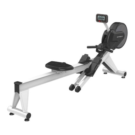
1.CRW800 Outlines... -
Page 7: Crw800 Electronic Parts
Electronic Parts CRW800... -
Page 9: Electrical Configurations
3.Electrical Configurations... - Page 10 Part Name Part Description Console Interface that controls all functions of the Rower. Tension motor It can change to increase or decrease resistance level of brake. General Information Part Name Part Description Console Contain Keys control and LCD Display. Main controller Include power supply and motor driver control circuit. Tension motor Work voltage: DC 4.0~6.0V Control resistance increases and decreases.
-
Page 11: Crw800 Product Operation
4. CRW800 Product Operation... -
Page 13: Function Description
4-1 Function Description stroke/min s/m value shows the equivalent strokes per minute. Time 1. It shows the time. 2. Range of time: 00:00~99:59(minute: second). 3. The time is accumulated for each workout mode. 4. When time is set to count down, it shows the time remaining. Distance 1. - Page 14 Watts 1. The Watt range is 0~2000. 2. When the numbers over 999 to four digits, the display would use point to show digit in thousands. E.g. 1000 shows 1.00, 1009 shows 1.01, 1240 shows 1.20, 1250 shows 1.25, 2000 shows 2.00, etc. LEVEL 1.
-
Page 15: Key Button Function
4-2 Key button Function All Keys 1. Any valid key button pressed will generate a beep sound. 2. When in power off mode, pressing any key button turns on the console. MODE Key 1. Under idle mode, pressing “MODE” key each time switches the workout mode with the following sequence: MANUAL →DISTANCE →TIME →CALORIES →20/10 INTERVAL →10/20 INTERVAL→CUSTOM INTERVAL→... - Page 16 Reset Key 1. Pressing this key button under stopping mode, the image switches to the idle mode. 2. The reset key button is valid only in stopping mode. 3. Under any mode, pressing this key button for 3 seconds turns on the console again.
-
Page 17: Operating Instruction
4-3 Operating Instruction 1. The screen is with full display and the buzzer beeps for two seconds after turning on. Pressing “Start” button goes directly to “Manual” workout mode or pressing “MODE” button to switch and select a workout mode with the workout sequence shown as below: MANUAL →DISTANCE →TIME →CALORIES →20/10 INTERVAL →10/20 INTERVAL→CUSTOM INTERVAL→... - Page 18 3. To choose target distance count-down Distance workout mode (Fig. 3-1) 1. Use UP/DOWN buttons to adjust and set the workout distance. The default distance is 100M with increment of 50M up or down. Press Start/Stop button to confirm the setting and start the workout mode. 2.
- Page 19 5. To choose target calorie count-down Calories workout mode (Fig. 5-1) 1. Use UP/DOWN buttons to adjust and set the target calorie. The default value is 100 with increment of 10 up or down. Press Start/Stop button to confirm the setting and start the workout mode.
- Page 20 7. To choose 10/20 INTERVAL workout mode (Fig. 7-1) 1. The image at the center of LCD: 10 seconds (Exercise)/20 seconds (Rest) 2. Pressing Start/Stop button starts the workout mode. 3. The image at the center of LCD shows time count-down of current workout and wave (Fig. 7-2) or rest time count-down and mark (Fig. 7-3). 4.
- Page 21 9. To choose Fat Burn workout mode (Fig. 9-1) 1. Pressing Start/Stop button and begins the workout mode or setting the workout time. Use UP/DOWN buttons to adjust the time. The increment of adjustment is 5-minute (99:00maximum). Press Start/Stop button to start the workout mode. 2.
- Page 22 11. To choose Strength workout mode (Fig. 11-1) 1. Pressing Start/Stop button and begins the workout mode or setting the workout time. Use UP/DOWN buttons to adjust the time. The increment of adjustment is 5-minute (99:00maximum). Press Start/Stop button to start the workout mode. 2.
-
Page 23: Crw800 Unit Block Diagrams
5. CRW800 Unit Block Diagrams... -
Page 25: Crw800 Basic Connections And Wiring
6-1 Display Board PCB Component Locations 6. CRW800 Basic Connections and Wiring... -
Page 26: Pcb Board Top
6-1-1 PCB BOARD TOP 6-1-2 PCB BOARD BOTTOM... -
Page 27: Tension Motor (Gear Motor) Connector Definition Function
6-1-3 TENSION MOTOR (GEAR MOTOR) CONNECTOR DEFINITION FUNCTION... -
Page 29: Generator Controller Connector Definition Function
6-1-4 GENERATOR CONTROLLER CONNECTOR DEFINITION FUNCTION GENERATOR INPUT 1 : AC 2 : N/A 3 : AC OUTPUT DC 1 2 3 1: POSITIVE 2: N/A 3: NEGATIVE... -
Page 30: Crw800 Error Messages / Troubleshooting
7. CRW800 Error Messages / Troubleshooting... -
Page 31: Error Codes
7-1 Error Codes Error Message Code Problem Description Console (Electronic Desk) EEPROM failure Cable tension communication error... -
Page 32: Prepare Tools
7-2 Prepare tools Multi-meter... -
Page 33: Error Message
7-3 Error Message Error code: E1 Description of the Situation When the screen displays "E1" "RAM ERROR" message, it means that the system console EEPROM failure, all functions are disabled. Troubleshooting Replace the console (Electronic Desk) - Page 34 Error code: E2 Description of the Situation When the "E2" "MOTOR ERROR" message is displayed, the communication with the cable tensioner is abnormal and all functions are stopped. Cable tensioner operation Device Description Console When you press the UP or DOWN key while in program mode, the LEVEL value displayed on the console display increases or decreases.
- Page 35 Cable tensioner fault / Voltage measurement procedure Place the multifunction meter at 12VDC. Place the probe in the motor control line on the drive board (the red probe is blue wire and the black probe is green wire). Turn on the power of device to tension motor. The console display lights. Press the LEVEL UP measurement to the normal reading: +4.0 ~ 6.0VDC, motor action, resistance increases.
-
Page 36: Maintenance Menu In The Console Software
7-4 Maintenance menu in the console software In the IDLE MODE, press UP and DOWN key for 3 seconds into the engineering mode one. Pressing the RESET key at any time returns to IDLE MODE. Enter the engineering mode one, do the LCD byte display test, each byte lit sequentially, after testing, directly into the main menu screen. Console window displayed "FUN", press MODE to enter option : Menu Item... -
Page 37: Troubleshooting Quick Lookup Table
7-5 Troubleshooting Quick Lookup Table Happening Caused Processing Step LCD display does not shine, incomplete or 1. LCD backlight damage. 1. Check the battery. imperfect 2. Console power is too low. 2. Replace the new LCD module or the control electronics. 3. -
Page 38: Console (Electronic Desk) Problem
7-6 Console (Electronic Desk) problem The normal operation of the console screen will be normal display, if not light up check the generator power is the normal power supply or change another one to check is work or check the generator controller is correctly, the controller have output voltage, and then check all the wire is indeed Plug in the console, the console cover removed to check whether all the wires inserted in the correct location, and check whether the wire fracture. -
Page 39: Light Sensor Problem
7-7-3 Light sensor problem A、 Check that the receiving board is in the correct position. B、 Check whether the light-emitting point and the receiving point are obstructed by dust. C、Check the cable connection. D、Replace the light sensor module. 7-7-4 RF handheld board problem A、... -
Page 40: Circuit Diagram(Crw800)
9.Circuit diagram(CRW800) -
Page 42: Exploded View (Crw800)
10.Exploded View (CRW800) -
Page 44: Part Replacement Guide
11.Part Replacement Guide... -
Page 45: Chain Cover &Galvanized Iron Net Replacement
11-1 Chain Cover &Galvanized iron net replacement. Step 1: Remove the Ø 5 × 16L_Tapping Screw(111) x2pcs from the Chain Cover (L) (71) by using Phillips Head Screw Driver, take apart the 3.5 × 12L_Sheet Metal Screw(112)x9pcs from the Chain Cover (R) (72), and then it works to take apart the Chain Cover (L) (71) completely. - Page 46 Step 4: Take out the Galvanized iron net (L) and Galvanized iron net (R) from the Chain Cover (L) and Chain Cover (R) and make it straight from the hole. Noted: It can be taken out the single chain cover and Galvanized iron. Step 5: To do the reverse of above steps to install Chain Cover (L) (71) and Chain Cover (R) (72).
-
Page 47: Console & Console Holder Assembly Replacement
11-2 Console & Console Holder Assembly replacement. Step 1: Take out the 3.5 × 12L_Sheet Metal Screw (112)x4pcs from the Console(43) by using the driver to the Top cover of Console(43), and then remove the 500m/m Computer Cable (Upper) (44) and wireless cables or receivers. - Page 48 Step 4: To do the reverse of above steps to resume the console assemble (43). Be noticed the processing of pass through the 3/8" × UNC16 × 3-3/4"_Socket Head Cap Bolt (83) and 500m/m Computer Cable (Upper), which may interfere with each other, need techniques.
-
Page 49: Handle Bar & Controller Assembly Replacement
11-3 Handle bar & Controller Assembly replacement. Step 1: Take out the 3.5 × 12L_Sheet Metal Screw (112) x2pcs and Sheet Metal Screw (132) x2pcs from the Controller Assembly (36) by using the driver (see figure 1), and pass the Handle through the Ribbon Roll (30). -
Page 50: Flywheel Pulley、Latch &Spring Latch Replacement
11-4 Flywheel Pulley、Latch &Spring Latch replacement. Step 1: Adjust the resistance to the highest on the Console and remove the Power Cord. Take out the Chain Cover (L)(71). Chain Cover (R)(72) 、 Handle(10) 、 Controller Assembly (36) and Console Holder Assembly (7) with Console Assembly (43). - Page 51 Step 5: Take out the M5 × 10L_Phillips Head Screw (86) x 2pcs by using driver. Separate the Attaching Plate (8R) with Bearing (6201 UOU). Step 6: Remove the Ø 20 x1.2t _C Ring(108) by clip and also Ø 20 × 29 × 0.3T_Wave Washer(96), Spring Latch(27) and Latch(26). Step 7: Be careful of the steps when reassemble the parts back.
- Page 52 Step 8: To mount generator belt to generator pulley. Step 9: To insert the Idle Wheel Screw to the generator Fixing Plate then locking the generator with a bolt (M6 *1.0*18L) and a flat washer. Step 10: To adjust the nut of idle wheel screw to the right tension which the generator belt won’t skidding. Step 11: Test with pull the handle bar to make sure there won’t be any noise.
-
Page 53: Fan & Flywheel Replacement
11-5 Fan & Flywheel replacement. Step 1: Adjust the assistance of console to the highest and remove the power cord. Take out the Chain Cover (L)(71)& Chain Cover (R)(72). Step 2: Pull out the Steel Cable (66) from the Flywheel(23). Step 3: Use 10/15m/m Wrench to loose M6 ×... -
Page 54: Gear Motor & Steel Cable Replacement
11-6 Gear Motor & Steel Cable replacement. Step 1: Adjust the assistance of console to the highest and remove the power cord. Take out the Chain Cover (L)(71)& Chain Cover (R)(72). Step 2: Pull out the Steel Cable (66) from the Flywheel (23). Step 3: Use driver to take out Ø... -
Page 55: Pedal、Pedal Plate & Wire Tie Mount Replacement
11-7 Pedal、Pedal Plate & Wire Tie Mount replacement. Step 1: Use 5m/m Wrench to take out the M8 × P1.25 × 12L_Button Head Socket Bolt(123)x6pcs, Ø 5/16" × Ø 18 × 1.5T_Flat Washer(122)x6pcs. Release the Pedal (L) & (R), Pedal(68), Pedal Plate(69) and Wire Tie Mount(67). -
Page 56: Aluminum Track、Seat &Rear Stabilizer Replacement
11-8 Aluminum Track、Seat &Rear Stabilizer replacement. Step 1: Use the driver to take out M5 × 10L_Phillips Head Screw(85)x3pcs and Connecting Cover(63). Step 2: Use 5m/m Wrench to take out the M8 × P1.25 × 12L_Button Head Socket Bolt(123)x6pcs, Ø 5/16" × Ø 18 × 1.5T_Flat Washer(122)x6pcs. Release the Aluminum Track(51), Seat sets(49)(16)(53)(54) and Rear Stabilizer(3). - Page 57 Step 5: Use 6m/m Wrench &14m/m Wrench to take 3/8" × UNC16 × 1-1/4"_Button Head Socket Bolt(105), 3/8" × 11T_Nyloc Nut(106) and Pulley(54) apart. Step 6: Use the driver to take M6 × 15L_Phillips Head Screw(124), Seat(49) and Seat Attaching Board(16) apart. Step 7: To do the reverse of above steps to resume parts.
-
Page 58: Folding End Assembly & Seat Up/Down Adjustment Knob Replacement
11-9 Folding End Assembly & Seat Up/Down Adjustment Knob replacement. Step 1: Remove Aluminum Track(51)& Pedal (L)(R). Step 2: Use 6m/m Wrench to take M8 × P1.25 × 15L_Socket Head Cap Bolt(98)x2pcs and Folding End Assembly(6) apart. ※ Please note it is not allowed to take out 2pcs of M8 × P1.25 × 15L_Socket Head Cap Bolt(98), please get a new piece of M8 × P1.25 × 15L_Socket Head Cap Bolt(98) to lock the original position. Follow the same steps to get another one. - Page 59 Step 5: Use 13m/m Wrench to remove the M8 × P1.25 × 13T_Cap Nut(100)x2pcs, M8 × P1.25 × 20L_Hex Head Bolt(99)x2pcs and take Tension Spring(48) and Main Frame(1) apart. Step 6: Use 8m/m Wrench to remove the 3/8" × UNC16 × 1"_Socket Head Cap Bolt) (101)x2pcs, Ø 3/8" × 20 × 3.0T_Flat Washer(102)x2pcs and take Seat Stop Axle(15) and Tension Spring(48) apart. Step 7: To do the reverse of above steps to resume parts...
-
Page 60: Batteries Replacement
11-10 Batteries replacement. Step 1: Use a screwdriver to remove a screw of battery cover on the back of console then replace batteries. -
Page 61: Generator Motor Replacement
11-11 Generator motor replacement. Step 1: Please follow the steps of Chain cover replacement to take off Chain cover. Step 2: To loose the nut (M8*7T) which locking with the idle wheel bolt, then remove the button socket cap screw and take off the generator. Step 3: To do the reverse of above steps to install the generator back. -
Page 62: Controller Board Replacement
11-12 Controller board replacement. Step 1: Lie down the machine. Step 2: Use a screwdriver to remove 4 screws(M5*10L). Step 3: Unplug the control wire then replace the controller board. Step 4: To do the reverse of above steps to install back. -
Page 63: Crw800 Troubleshooting
12. CRW800 Troubleshooting... -
Page 64: The Console Display Troubleshooting
12-1 The Console Display troubleshooting Q: Count Times doesn’t show in display. A: Please check the connections with optical coupler Board (34) or the connection of all wires. Q: The console doesn’t display. A: Please check the connection with 750m/m DC Power Cord(39), Gear Motor(35), and 500m/m Computer Cable (Upper)(44). -
Page 65: The Resistance Level Can't Adjust Troubleshooting
12-2 The Resistance Level can’t adjust troubleshooting Please check Controller Assembly(36) and Console Assembly(43) if there’s no adjustable resistance separately. If it is the problem of Controller Assembly(36), please refer to step 1. If it is the problem of Console Assembly(43), please refer to step 3. 1.Please follow the steps of instruction manual or the message on the sticker to proceed the calibration of RF module. -
Page 66: Troubleshooting For Not Smooth When Operating
12-3 Troubleshooting for not smooth when operating Q: Ribbon Roll can’t Spring Back. A: Release the Chain Cover (R)(72) and check the Latch(26). If the ribbon roll can spring back, the problem could be broken on the other side. Please pull it out and check. If the Latch(26) cannot spring back, please release the Attaching Plate (8R) to check the connections of Spring Latch(27~2) and Latch(26). -
Page 67: Troubleshooting For Other Problems
12-4 Troubleshooting for Other problems Q: Slide works not smoothly. A: Please follow below steps until the slide works. 1. Please clean Aluminum Board(52)& Aluminum Track Pulley(53). 2. Please loose 3pcs of 3/8" × 11T_Nyloc Nut(106). 3. Check and replace Aluminum Track Pulley(53) or Pulley(54). Q: Noise.
Need help?
Do you have a question about the CRW800 and is the answer not in the manual?
Questions and answers