
Related Manuals for PushCorp 0612

Summary of Contents for PushCorp 0612
- Page 1 0612 High Torque Servo Motor Series Manual ORP, Dallas, Texas March, 2023...
- Page 2 Doing so will damage the motor and power amplifier. All PushCorp, Inc. electrical cables are rated for high twist and flex robotic applications with a minimum cable bending radius specification of 125mm (5 in). Cable damage resulting from failure to abide by this specification will not be covered under warranty.
-
Page 3: Table Of Contents
0612 Servo Motor Series Manual ORP, Table of Contents 1.0 LIMITED WARRANTY...................1 2.0 GENERAL OVERVIEW..................3 3.0 INSTALLATION & OPERATION................4 3.1 Mounting the 0612........................... 4 3.1.1 Mounting to an AFD1100/80......................4 3.1.2 Mounting Directly to a Robot......................7 3.2 Media and Tool Presentation......................7 3.3 Tool and Media Specification...................... -
Page 4: Limited Warranty
Dallas, Texas 75218 Shipping Address: 3001 W. Kingsley Rd. Garland, Texas 75041 Who receives this warranty (purchaser): The original purchaser (other than for purposes of resale) of the PushCorp, Inc. product What products are covered by this warranty: PushCorp, Inc. - Page 5 0612 Servo Motor Series Manual ORP, Responsibilities of the purchaser under this warranty: A. Deliver or ship the PushCorp, Inc. product or component to PushCorp, Inc. Service Center, Dallas, TX. Freight and insurance costs, if any, must be borne by the purchaser.
-
Page 6: General Overview
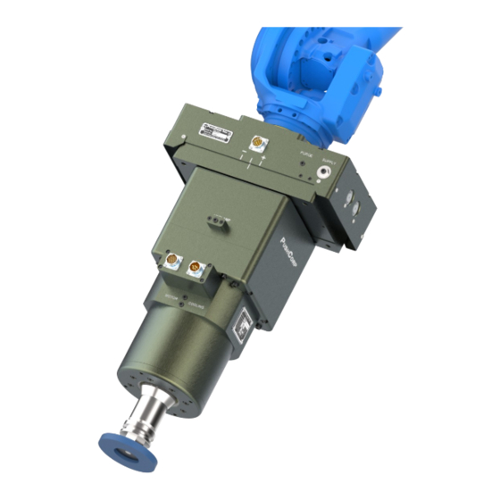
2.0 General Overview The PushCorp 0612 Servo Motor is capable of continuously producing 12 horsepower, and spinning up to 6000 rpm. The 0612 series includes three versions; an SM0612 manual collet, an automatic version with a collapsing collet (STC0612) and another automatic version which clamps a BT40 toolholder (STC0612-BT40). -
Page 7: Installation & Operation
Carriage with two brackets and four (4), M8x1.25x25mm, Socket Head Cap Screws. The 0612 is positioned on the Carriage with the Foot Bracket while the Front Bracket is attached to the forward mounting holes. The Clamping Screw on the Front Bracket should be loose to allow sliding movement along the motor. - Page 8 0612 Servo Motor Series Manual ORP, By rotating the 0612 90 degrees to the Carriage, a Cross-Axis configuration can be achieved as shown in Figure 2. The unit is attached using the same fasteners and methodology as the Parallel-Axis configuration.
- Page 9 0612 Servo Motor Series Manual ORP, Figure 2: 0612 Cross-Axis Configuration Figure 3: 0612 Perpendicular-Axis Configuration Copyright PushCorp, Inc. 2015. All rights reserved.
-
Page 10: Mounting Directly To A Robot
ORP, 3.1.2 Mounting Directly to a Robot For some processes compliance and force control are not required. The 0612 can be mounted directly to the robot and the system can be operated in position mode. This robotic system is equivalent to a 5-axis machining center with a very large work volume and lower positional accuracy. -
Page 11: Tool And Media Specification
Shaft Clamping Surface and taper must be shorter than the Collet depth. When using the Collet face for positioning some form of compliance must be used on the Tool Cradle to prevent wedging the Collet in too tightly, or damaging the motor bearings. Copyright PushCorp, Inc. 2015. All rights reserved. - Page 12 0612 Servo Motor Series Manual ORP, Figure 6: STC0612 Collet Drawing Figure 7: SM0612 Collet Drawing Copyright PushCorp, Inc. 2015. All rights reserved.
-
Page 13: Stc0612-Bt40 Toolholder Specification
BT40 toolholder to handle special media (See Figure 9 for toolholder dimensions). The toolholder must be equipped with a Parlec (www.parlec.com) retention knob, part number 4020TRK, or equivalent. Figure 10 shows the Parlec retention knob with the required dimensions. Copyright PushCorp, Inc. 2015. All rights reserved. - Page 14 0612 Servo Motor Series Manual ORP, Figure 9: BT40 Toolholder Dimensions Figure 10: BT40 Retention Knob Copyright PushCorp, Inc. 2015. All rights reserved.
-
Page 15: Sm0612 Collet Operation
To remove the Collet, first unscrew the Collet Nut from the Motor Shaft. After the Collet Nut is unscrewed, press on the face of the Collet while simultaneously pushing sideways on the back of the Collet until it disengages from the Collet Nut. See Figure Copyright PushCorp, Inc. 2015. All rights reserved. -
Page 16: Pneumatic Connection
3.5 Pneumatic Connection All STC versions of the 0612 require a dry, non-lubricated, filtered air supply, with a minimum pressure of 90 psi (6.2 bar) and a maximum pressure of 100 psi (6.9 bar). Failure to provide supply air to these specifications can degrade performance and will void any warranty repairs concerning pneumatic components. - Page 17 An electrically operated pneumatic valve is normally used in an automated workcell. PushCorp highly recommends the installation of a Pressure Switch in the Supply Line to the STC. This switch should not allow the unit to start if there is any pressure in the Supply Line. Pressure in the line will cause internal components to come into contact.
- Page 18 0612 Servo Motor Series Manual ORP, NOTE: PushCorp highly recommends the use of flexible polyurethane tubing as opposed to nylon tubing. This is because nylon tubing tends to crimp shut when it is bent. To remove the Unclamp Supply Line for service, make sure the air pressure is discharged, then while pushing inward on the fitting's plastic ring, simultaneously pull the tubing out.
-
Page 19: Electrical Connections
ORP, 3.6 Electrical Connections The 0612 servo motor has two electrical connections, the Motor Power and Motor Feedback (See Figure 14). If PushCorp supplies the cables and amplifier the tool should be easily connected to the amplifier. If the customer wishes to use their own cables and/or amplifier the pin-outs for the Motor Power and Motor Feedback connectors are shown below in Figure 14. -
Page 20: S724 Servo Amplifier - Default Electrical Connections
0612 Servo Motor Series Manual ORP, 3.6.1 S724 Servo Amplifier – Default Electrical Connections This amplifier is already properly configured for a PushCorp spindle. No further configuration is required if the below settings will work for your application. Analog Velocity Mode... -
Page 21: Hall Motor Timing Chart
0612 Servo Motor Series Manual ORP, 3.6.2 Hall Motor Timing Chart Figure 15: Hall Motor Input/Output Copyright PushCorp, Inc. 2015. All rights reserved. -
Page 22: Motor Cooling
ORP, 3.7 Motor Cooling The 0612 Series has a compact, high torque, 12.0 Hp (9 kW) Servo Motor which requires water cooling. The motor is designed to operate below a temperature of 176 F (80 C). The optimal motor temperature range is 122 – 140 °F (50 – 60 °C). The 0612 contains cooling channels in the Motor Housing surrounding the motor stator. -
Page 23: Monitoring Motor Temperature
To facilitate this, the 0612 Series has a thermistor that is imbedded in the motor windings. The thermistor connection is provided on the Motor Feedback Connector as shown in Figure 14. -
Page 24: Motor Acceleration/Deceleration
The amount of time allowed to reach the desired speed or stop will directly effect the life of the motor. PushCorp recommends a smooth, linear velocity ramp with a minimum period of one second be used to accelerate to full speed or to decelerate to zero speed. -
Page 25: Stc Spindle Tool Change
ORP, 3.10 STC Spindle Tool Change PushCorp STC spindles have the ability to switch tool holders out using pneumatic actuation. The STC0612 uses a keyless BT40 toolholder, which provides strong holding torque and tool retention. To properly change out a tool, the following steps are recommended to avoid damaging the spindle, toolholder or gripper fingers. - Page 26 0612 Servo Motor Series Manual ORP, Figure 18: STC Spindle Tool Change Sequence Copyright PushCorp, Inc. 2015. All rights reserved.
-
Page 27: Technical Specifications
M4 x .7 0.17 M5 x .8 0.21 M6 x 1 11.7 15.8 0.25 M8 x 1.25 29.0 39.3 0.33 M10 x 1.5 50.0 67.8 0.41 10.5 Specifications subject to change without notice. Copyright PushCorp, Inc. 2015. All rights reserved. -
Page 28: Preventative Maintenance Schedule
It is highly recommended to adhere to the preventative maintenance schedule in order help extend the longevity of the specified PushCorp, Inc. equipment. Failing to do so could cause a loss in functionality as well as a decrease in product life.
Need help?
Do you have a question about the 0612 and is the answer not in the manual?
Questions and answers