Table of Contents
Advertisement
Quick Links
Advertisement
Table of Contents

Related Manuals for Quest Controls 600


Summary of Contents for Quest Controls 600
- Page 1 Model 600 User’s Manual Rev 1.0 01/11/24...
-
Page 2: Table Of Contents
Front Panel Display/Keypad Operation ....................11 Run Mode ..........................11 3.1.1 Additional displays: ....................... 11 Comfort Mode ........................... 12 Lead Switch ..........................12 Programming the Model 600 ....................13 Program Menus ......................... 13 3.5.1 System Menu*........................13 3.5.2 Setpoint Menu........................15 3.5.3... - Page 3 Operational Heating Setpoint ....................23 Comfort Mode ........................... 23 Lead Switch Request ........................23 Econ Disable ..........................23 HVAC Shutdown ........................23 6.10 HVAC Mode ..........................24 6.11 Remote Alarm Monitoring ......................24 Troubleshooting ..........................24 Rev 1.0 01/11/24 Model 600 User Guide...
- Page 4 Appendix B – Control Output Matrix ......................35 Contact Information ............................ 36 Figure 1 - Enclosure Mounting Holes ......................2 Figure 2- Model 600 Wiring Diagram ......................4 Figure 3 – End of Line Resistor ........................6 Figure 4 – Single Stage HVAC Typical Installation ..................7 Figure 5 –...
- Page 5 Copyright © 2024 by Quest Controls, Inc. (Quest). The material discussed in this publication is the proprietary property of Quest. Quest retains all rights to reproduction and distribution of this publication. Specifications are subject to change without notice. Rev 1.0 01/11/24 Model 600 User Guide...
-
Page 6: Overview
2.1 Mounting Mount the Model 600 on an interior wall in a location that is accessible for wiring and attainable to the color touchscreen on the front of the system. It is recommended to mount the controller no higher than six feet above the finished floor so that the touchscreen is easily accessible. - Page 7 7.09" Figure 1 - Enclosure Mounting Holes Rev 3.1 01/11/23 - 2 - Model 600 User Guide...
-
Page 8: Powering The System
2.2 Powering the System The Model 600 has three sources for powering the system. All three can be used simultaneously to provide redundancy to the system. The Model 600 gets 24VAC power from each HVAC system being controlled when the R (24vac hot) and C (24VAC common) terminals are connected to the system. The system monitors the presence of the 24VAC voltage from the HVAC unit to determine if power is lost, requiring a switch of the lead HVAC system. -
Page 9: Input/Output Function
Figure 2- Model 600 Wiring Diagram Input/Output Function The following matrix describes each input and output and what they are used for. Use this guide to determine how you want to wire your Model 600 system. 2.4.1 Input Definitions Name... -
Page 10: Control Output Definitions
RS485 networks require an end of line resistor (EOL) to be present on the end devices of a daisy chain network. For a Model 600 at the end of the network, add a 120-ohm EOL resistor between D0 - and D1+ terminals. -
Page 11: Wiring Types
Typical installation drawings Below are some typical installation drawings for HVAC systems with Integrated Economizer control and when the Model 600 is controlling the economizer damper directly. Please contact Quest Controls for assistance if your application differs from these examples. - Page 12 CONTROL VOLTAGE LOSS HVAC LOCKOUT SMOKE ALARM OUTDOOR HIGH TEMP L2 AIR SENSOR LOW TEMP HIGH TEMP L1 ALARM SHOWN WIRED NORMALLY CLOSED Figure 4 – Single Stage HVAC Typical Installation Rev 3.1 01/11/23 - 7 - Model 600 User Guide...
- Page 13 CONTROL VOLTAGE LOSS HVAC LOCKOUT SMOKE ALARM OUTDOOR HIGH TEMP L2 AIR SENSOR LOW TEMP HIGH TEMP L1 ALARM SHOWN WIRED NORMALLY CLOSED Figure 5 – Two Stage HVAC Typical Installation Rev 3.1 01/11/23 - 8 - Model 600 User Guide...
- Page 14 CONTROL VOLTAGE LOSS HVAC LOCKOUT SMOKE ALARM OUTDOOR HIGH TEMP L2 AIR SENSOR LOW TEMP HIGH TEMP L1 ALARM SHOWN WIRED NORMALLY CLOSED Figure 6 - Marvair HVESA Typical Installation Rev 3.1 01/11/23 - 9 - Model 600 User Guide...
- Page 15 1. SET JADE CONTROLLER TO ECONOMIZE AT 74 DEGREE OSA 2. CONFIGURE SETUP FOR SINGLE STAGE INTEGRATED OR QUEST MODE ECONOMIZER. 3. OSA SENSOR MUST BE CONNECTED FOR QUEST MODE Figure 7 – Bard H**4 System Wiring Diagram Rev 3.1 01/11/23 - 10 - Model 600 User Guide...
-
Page 16: Front Panel Display/Keypad Operation
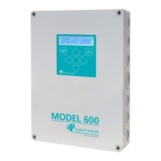
3 Front Panel Display/Keypad Operation The Quest Model 600 has a 2X16 character backlit LCD and five buttons for status review and programming. Additionally, there are separate keys for lead switch and comfort mode operation. The backlight is normally off but will turn on when any key is pressed. The backlight will turn off after a few seconds of no keys being pressed. -
Page 17: Comfort Mode
Being used. Note the values shown are the active value and can change based on comfort mode or being remotely set through Modbus. The Econ setpoint will only be show if the Model 600 is defined to use Econ Mode. -
Page 18: Programming The Model 600
The unit switched to lead will remain in the lead position until the lead switch timer elapses or an alarm condition that causes a lead switch. 3.4 Programming the Model 600 Press and hold the left and right arrow simultaneously until the display shows the enter password option. - Page 19 If a fan is defined as auto, then this is the delay after a call for cooling or heating before the fan turns off. Restart Delay 0-900 seconds (0) After a power failure to the Model 600 the system will wait this delay time before starting control operations. Modbus Address 0-247 (0)
-
Page 20: Setpoint Menu
Stg Min Off Time 30-600 (120) The number of seconds to wait once a stage or cooling or heating is off before it can come back on. Rev 3.1 01/11/23 - 15 - Model 600 User Guide... -
Page 21: Economizer Menu
Generator Run input. Select option based on how the Closed, Normally input is wired. Disable prevents the alarm condition Open from functioning. This alarm is available on display and Modbus only. Rev 3.1 01/11/23 - 16 - Model 600 User Guide... -
Page 22: Bypass Menu
3.5.6 Run Option Selecting Run puts the Model 600 back in run mode. Note: some changes require a restart. The Display will show “Restarting Soon” to indicate it is storing changes to flash and will reboot with the new configuration. -
Page 23: Controlling Temperature
When using the average or high of the two sensors, the system will use that function provided both sensors have valid readings. If one sensor is in error, then the Model 600 Controller will only use the sensor with valid readings. If there is no valid reading from either sensor then the system will report a sensor error on the display, turn the supply fans on and turn off heating and cooling. -
Page 24: Heating Mode
4.5 Heating Mode The Model 600 Controller has two setpoints for heating mode. Heating stage 1 will be enabled when the controlling temperature is below the heating setpoint. If the temperature continues to lower to where the controlling temperature is below the heat 2 threshold (heating spt – heat 2 delta) then heat stage 2 will be enabled. -
Page 25: Integrated Econ Control
Integrated economizer control means the economizer is being controlled by the HVAC system. The Model 600 Controller will decide to turn on stage 1 of cooling. The HVAC system will then decide to use economization or mechanical cooling. If temperature continues to rise, the Model 600 Controller will turn on output 2 to force mechanical cooling. -
Page 26: Low Temperature
HVAC unit. When this input is active, the controller will turn off the mechanical cooling of the affected unit. In addition, if the affected unit is the lead, the Model 600 will switch the lead unit. Alarm Output 6 is used to indicate a control voltage alarm has occurred on either unit along with an alarm message on the front display and status via Modbus. -
Page 27: Hydrogen Alarm
This register would normally display the value of the outside air temperature on the Model 600, but this register can also be written to so that a single Rev 3.1 01/11/23... -
Page 28: Operational Cooling Setpoint
OSA sensor can be used on one device and be sent to other Model 600 units by the Modbus polling agent. 6.3 Operational Cooling Setpoint Modbus holding register 102 is used to display the current cooling setpoint. This will either be the locally stored value, or a polling agent can write a value to this register. -
Page 29: Hvac Mode
Tip: you can use the built-in Windows calculator in programmer mode to do the calculations. The Model 600 will countdown and return to automatic mode at the end of the bypass time. Alternatively, you can write a 0 to the register to clear the bypass. - Page 30 “Cold Sense”, continue holding the cold start button until you see Cold Start on the display. Release the buttons at this time. This action will reset the Model 600 and return all settings to their factory defaults. The Model 600 will then need to be reconfigured with the desired settings.
- Page 31 8 Model 600 Specifications Specifications Part Number 151112 Mounting Wall mount Enclosure Color: Grey Material: Polycarbonate with knockouts on all sides Inputs Digital Inputs: (2) 24vac input from HVAC, (7) dry contact closures. Analog Inputs: Temperature sensors (3) Thermistors sensor ± 1°F (0.5°C) 4-20mA Input (1) –...
- Page 32 HVAC 1 Control Voltage Loss 0 = off and 1 =on HVAC 2 Control Voltage Loss 0 = off and 1 =on HVAC 1 Econ Status 0 = off and 1 =on Rev 3.1 01/11/23 - 27 - Model 600 User Guide...
- Page 33 1 off, 0 on. Output energized when not in alarm. Low Building Temp Alarm 1 off, 0 on. Output energized when not in alarm. Smoke Alarm 1 off, 0 on. Output energized when not in alarm. Rev 3.1 01/11/23 - 28 - Model 600 User Guide...
- Page 34 Enumerated low byte: 1 = Heat 2, 2 = Heat 1, 3 = Off, 4 = Econ 1, 5 = Model 600 Control Mode word Econ 2, 5 = Cool 1, 6 = Cool 2, 7 = Cool 3, 8 = Cool 4...
- Page 35 0 = inactive, 1 = active, any write HVAC 2 Control Voltage Loss word clears active alarm 0 = inactive, 1 = active, any write Smoke alarm status word clears active alarm Rev 3.1 01/11/23 - 30 - Model 600 User Guide...
- Page 36 0 – 9600, 1 – 19200, 1011 Baud Rate word 2 – 38400, 3 – 57600, 4 – 76800 1012 Front Panel Access Code word 0 = disable, 11-99 to enable Rev 3.1 01/11/23 - 31 - Model 600 User Guide...
- Page 37 RH Econ Disable SPT word 0-240 Minutes, 0 = disable 1119 Comfort Mode Minutes word 0-336 hours, 0 = disable 1120 Lead Switch Hours word 30-600 Seconds 1121 Stage Min On Secs word Rev 3.1 01/11/23 - 32 - Model 600 User Guide...
- Page 38 2 = normally closed (open alarms) Misc. 1300 Product ID word 1301 Firmware Revision word A.B.C.D in 4-bit numbers Must write 57005 to data register 1302 Reset word for reset Rev 3.1 01/11/23 - 33 - Model 600 User Guide...
- Page 39 Rev 3.1 01/11/23 - 34 - Model 600 User Guide...
- Page 40 G, Y1, O COOL1 G, Y1, 2, O G, Y1, 2, O COOL2 G, Y1, 2, O G, Y1, 2, O HEAT1 G, W G, W HEAT2 G, W G, W Rev 3.1 01/11/23 - 35 - Model 600 User Guide...
- Page 41 Fax: (941) 729-5480 Place Orders or Check Scheduling & Delivery: (941) 729-4799, option 3. Technical & Applications Support: (941) 729-4799, option 5 Repair and RMA Support: (941) 729-4799, option 6 Rev 3.1 01/11/23 - 36 - Model 600 User Guide...
Need help?
Do you have a question about the 600 and is the answer not in the manual?
Questions and answers