Table of Contents
Advertisement
Quick Links
Advertisement
Table of Contents

Related Manuals for Quest Controls 400


Summary of Contents for Quest Controls 400
- Page 1 Model 400 User’s Manual Rev 1.2 08/19/22...
-
Page 2: Table Of Contents
RS485 End of Line resistor ......................5 Front Panel Display/Keypad Operation ....................7 Run Mode ............................7 3.1.1 Additional displays: ....................... 7 Programming the Model 400 ......................7 3.2.1 Programming flow: ....................... 8 3.2.2 Submenus ..........................8 Remote Communications........................9 Controlling Temperature ...................... - Page 3 Figure 2 - Connection Descriptions ....................... 3 Figure 3 - Typical Wiring Diagram ......................... 4 Figure 4 - Setting Communication Jumper ....................5 Figure 5 - Networking Model 400 Units to the ESB2 ..................6 Figure 6 - Programming Flow ........................8 Rev 1.2 08/19/22...
- Page 4 Copyright © 2020-2022 by Quest Controls, Inc. (Quest). The material discussed in this publication is the proprietary property of Quest. Quest retains all rights to reproduction and distribution of this publication Specifications are subject to change without notice. Rev 1.2 08/19/22 Model 400 User Guide...
-
Page 5: Overview
The Model 400 remotely communicate through Modbus RTU to the ESB2 or any other Modbus polling agent. The Model 400 contains an onboard temp sensor making it suitable for zone mounting and a remote input for panel mounting applications or when internal and external zone sensors are desired. The Model 400 includes inputs terminals for supply air, mixed air temperature, 4-20 milliamp for current sensing, and digital inputs for HVAC lockout and fan proof of run. -
Page 6: Installing The Mounting Plate
3. Remove the cover - The cover of the Model 400 is held on by four clips, two on the top and two on the bottom. Remove the cover carefully, as the cover may be snug and depressing the clips through the slot openings may help in getting the cover off. -
Page 7: Wiring
1/4” of insulation to expose conductor. Insert and tighten using the Wire Terminations diagram. 2. Connection Descriptions: For an additional 24VDC source to power the Model 400, 24VDC + This will power the unit and operate the analog outputs. - Page 8 3. Typical Wiring Diagram Figure 3 - Typical Wiring Diagram Rev 1.2 08/19/22 Model 400 User Guide...
-
Page 9: Rs485 End Of Line Resistor
RS485 networks require an end of line resistor (EOL) to be present on the end devices of a daisy chain network. For the Model 400 at the end of the network, add the included 120-ohm EOL resistor between D0 - and D1+ terminals. - Page 10 Enable EOL resistor on ESB2 if it is on one end of the daisy chain Install EOL resistor on last Model 400 in the daisy chain Figure 5 - Networking Model 400 Units to the ESB2 Rev 1.2 08/19/22 Model 400 User Guide...
-
Page 11: Front Panel Display/Keypad Operation
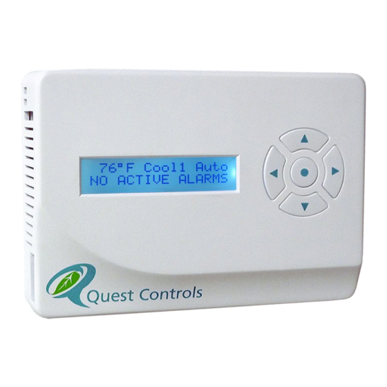
3 Front Panel Display/Keypad Operation The Quest Model 400 has a 2X16 character backlit LCD and five buttons for status review and programming. The backlight is normally off but will turn on with a press of any key. The backlight will turn off after a few seconds of no keys being pressed. -
Page 12: Programming Flow
Access Code: 11-99 (11) Prog Menu Access: Allow, Don’t Allow Alarm Menu HighTemp Alarm SPT: 70-140 (80) LoTemp Alarm SPT: 20-60 (50) Lockout Alarm: Disabled, Normally Open, Normally Closed FanFail Alarm: Disabled, Normally Open, Normally Closed Rev 1.2 08/19/22 Model 400 User Guide... -
Page 13: Remote Communications
Heat Min Off Time: 60-600 (120) Run: Puts the Model 400 back in run mode. Note: some changes require a restart. The Display will show “Restarting Soon” to indicate it is storing changes to flash and will reboot with the new configuration. -
Page 14: Controlling Temperature
Lead/Lag operation between multiple units and or change the setting based on time or occupancy. Writing a value of 65535 will cause the Model 400 to use the locally stored value of Modbus register 1100. -
Page 15: Operational Heating Setpoint
Lead/Lag operation between multiple units and or change the setting based on time or occupancy. Writing a value of 65535 will cause the Model 400 to use the locally stored value of Modbus register 1104. -
Page 16: Hvac Mode
When using the average or high of the two sensors, the system will use that function provided both sensors have valid readings. If one sensor is in error, then the Model 400 Controller will only use the sensor with valid readings. If there is no valid reading from either sensor then the system will report a sensor error on the display, turn the supply fan on and turn off heating and cooling. -
Page 17: Fan Control
5.3.1 Direct Econ control Direct control of the economizer means the Model 400 Controller will use the mixed air sensor to make decisions to modulate the OSA damper using the damper analog output. The mixed air sensor must be connected to the controller and operational for the control to function properly. If the mixed air sensor is in error, the controller can open the damper to 100% provided the outside air sensor reading is Rev 1.2 08/19/22... -
Page 18: Integrated Econ Control
Integrated economizer control means the economizer is being controlled by the HVAC system. In this case, the Model 400 Controller will decide to use the economizer and turn on stage 1 of cooling. The HVAC system will then decide to use economization or mechanical cooling. The mixed air sensor is not required for this mode to operate. -
Page 19: Heating Mode
6.4 HVAC Fan Failure The fan failure alarm will occur if the Model 400 Controller is configured for fan failure. When the controller calls for the fan to run and the fan feedback input is not active after 5 minutes then the Rev 1.2 08/19/22... -
Page 20: Cooling Failure
6.5 Cooling Failure When the Model 400 Controller is calling for mechanical cooling for the failure delay time and the supply temperature is greater than the cooling failure setpoint then the system will generate a cooling failure alarm. - Page 21 “Cold Start”. Release the buttons at this time. This action will reset the Model 400 and return all settings to their factory defaults. The Model 400 will then need to be reconfigured with the desired settings.
-
Page 22: Model 400 Specifications
9 Model 400 Specifications Specifications 150966-5 Wall mount directly or standard single gang electrical box Part Number Color: Quest white Mounting Material: Two-piece thermal molded plastic enclosure. All wiring is done on the mounting base and Enclosure the controller is pull-off. -
Page 23: Appendix A - Modbus Register Map
Digital Inputs Discrete Input 0 = off and 1 = on based on Reg Fan Proof of Run byte (FC2) 1203 0 = off and 1 =on based on Reg HVAC Lockout byte 1202 Rev 1.2 08/19/22 Model 400 User Guide... - Page 24 1001. (FC3/6/16) Write of 65535 will resume local operation. Outside Air Temperature word degrees Write will override internally calculated value. Operational Cooling Setpoint word 1100 Write of 65535 will resume local operation. Rev 1.2 08/19/22 Model 400 User Guide...
- Page 25 0 = inactive, 1 = active, any write Low temperature alarm status word clears active alarm 0 = inactive, 1 = active, any write HVAC Lockout alarm status word clears active alarm Rev 1.2 08/19/22 Model 400 User Guide...
- Page 26 2 – 38400, 3 – 57600, 4 – 76800 1010 Front Panel Access Code word 0 = disable, 11-99 to enable 1011 Front Panel Program Menu Lockout word 0 = allow, 1 = don't allow Rev 1.2 08/19/22 Model 400 User Guide...
- Page 27 Supply Fan Dwell time word 15-300 seconds 1121 Supply Fan minimum percentage word 0-100% 1200 High temperature level word 70-140 = degrees 1201 Low temperature level word 20-60 = degrees 1202 HVAC Lockout word Enumerated: Rev 1.2 08/19/22 Model 400 User Guide...
- Page 28 90-120 = degrees 1207 Heating Failure delay word 300-3600 seconds 1300 Product ID word 1301 Firmware Revision word A.B.C.D in 4-bit numbers Must write 57005 to data register 1302 Reset word for reset Rev 1.2 08/19/22 Model 400 User Guide...
-
Page 29: Appendix B - Control Mode Matrix
<fan mode> ON/Auto calc speed min pos. control temp < Cool off <fan mode> ON/Auto calc speed control temp < heat1 HEAT1 control temp < heat2 HEAT2 Rev 1.2 08/19/22 Model 400 User Guide... - Page 30 <fan mode> ON/Auto calc speed min pos. control temp < Cool off <fan mode> ON/Auto calc speed control temp < heat1 HEAT1 control temp < heat2 HEAT2 Rev 1.2 08/19/22 Model 400 User Guide...
-
Page 31: Contact Information
Main Number: (941) 729-4799 Fax: (941) 729-5480 Place Orders or Check Scheduling & Delivery: (941) 729-4799, option 3 Technical & Applications Support: (941) 729-4799, option 5 Repair and RMA Support: (941) 729-4799, option 6 Rev 1.2 08/19/22 Model 400 User Guide...
Need help?
Do you have a question about the 400 and is the answer not in the manual?
Questions and answers