Lincoln Electric LT-7 Service Manual
Lightweight tractor
Hide thumbs
Also See for LT-7:
- Technical specifications (4 pages) ,
- Operator's manual (89 pages) ,
- Operator's manual (88 pages)
Table of Contents
Advertisement
Quick Links
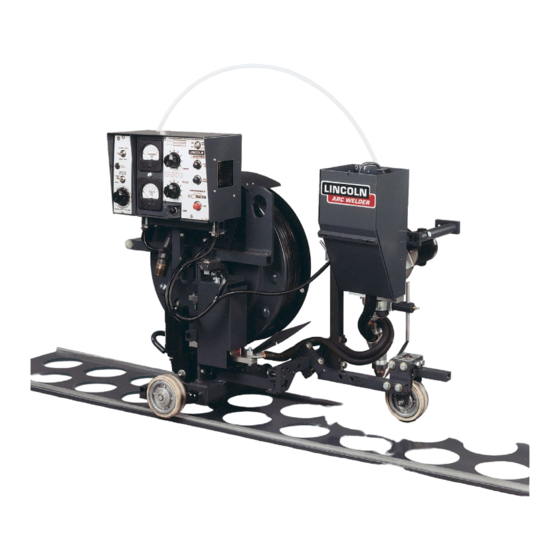
LT-7 LIGHTWEIGHT TRACTOR
For use with machines having Code Numbers:
7429 thru 11358
SERVICE MANUAL
SVM198-A
| Issue D ate 10-Jul
© Lincoln Global, Inc. All Rights Reserved.
NOTE: This manual will cover most of the troubleshooting and repair
procedures for the code numbers listed. Some variances may exist when
troubleshooting/repairing later code numbers.
Advertisement
Chapters
Table of Contents

Related Manuals for Lincoln Electric LT-7


Summary of Contents for Lincoln Electric LT-7
- Page 1 NOTE: This manual will cover most of the troubleshooting and repair procedures for the code numbers listed. Some variances may exist when troubleshooting/repairing later code numbers. LT-7 LIGHTWEIGHT TRACTOR For use with machines having Code Numbers: 7429 thru 11358 SERVICE MANUAL...
- Page 2 Miami, Florida 33135 or CSA Standard W117.2-1974. A Free copy of “Arc Welding Safety” booklet E205 is available from the Lincoln Electric Company, 22801 St. Clair Avenue, Cleveland, Ohio 44117-1199. BE SURE THAT ALL INSTALLATION, OPERATION, MAINTENANCE AND REPAIR PROCEDURES ARE PERFORMED ONLY BY QUALIFIED INDIVIDUALS.
- Page 3 5.e. Read and understand the manufacturer’s instructions for this equipment and the consumables to be used, including the material safety data sheet (MSDS) and follow your employer’s safety practices. MSDS forms are available from your welding distributor or from the manufacturer. 5.f. Also see item 1.b. LT-7 TRACTOR...
- Page 4 6.I. Read and follow NFPA 51B “ Standard for Fire Prevention During Welding, Cutting and Other Hot Work”, available from NFPA, 1 Batterymarch Park,PO box 9101, Quincy, Ma 022690-9101. 6.j. Do not use a welding power source for pipe thawing. Refer to http://www.lincolnelectric.com/safety for additional safety information. LT-7 TRACTOR...
- Page 5 4. Garder tous les couvercles et dispositifs de sûreté à leur place. talons sans revers, et chaussures montantes. 5. Toujours porter des lunettes de sécurité dans la zone de soudage. Utiliser des lunettes avec écrans lateraux dans les zones où l’on pique le laitier. LT-7 TRACTOR...
- Page 6 2004/108/EC. It was manufactured in conformity with a national standard that implements a harmonized standard: EN 60974-10 Electromagnetic Compatibility (EMC) Product Standard for Arc Welding Equipment. It is for use with other Lincoln Electric equipment. It is designed for industrial and professional use. Introduction All electrical equipment generates small amounts of electromagnetic emission.
- Page 7 Screening of the entire welding installation may be considered for special applica- tions. 1 _________________________ 1 Portions of the preceding text are contained in EN 60974-10: “Electromagnetic Compatibility (EMC) product standard for arc welding equipment.” LT-7 TRACTOR...
- Page 8 Parts Manual ..............P-117 LT-7 TRACTOR...
-
Page 9: Table Of Contents
Recommended General Options ............A-6 LT-7 TRACTOR... - Page 10 -40 to 185 (-40 to 50 (-40 to 85 GEARING WIRE FEED SPEED Range Wire Sizes 90:1 50-400 ipm (1.3 - 5.1m/min) 3/32” - 3/16” (2.4 4.8mm) Travel Speed Range 6 to 70 ipm (0.15 to 1.8 m/min) LT-7 TRACTOR...
-
Page 11: Product Overview
FEATURES • LT-7 Tractor feeds 3/32 to 3/16” (2.4 to 4.8 mm) solid wires, from 35 - 400 inches per minute (0.9 - 10.2 m/min) wire feed speed. • Calibrated tractor drive adjusts travel speeds from 6 to 70 inches per minute (0.12 to 1.8 m/min). -
Page 12: Recommended Processes And Equipment
Cables K1822-25 - 25 Ft. (7.6m) Wire Feeder Control Cable • Connects the LT-7 to power sources that have a 14 pin MS type connector (i.e.CV 655, DC 655 or DC 600) K1797-25 - 25 Ft.(7.6m) Control cable extension K1797-50 - 50 Ft.(15.2m) Control cable extension •... -
Page 13: Contact Nozzle Assemblies
3/32” to 3/16” (2.4-4.8mm). K231 K148A - Positive Contact Nozzle for 3/32 or 1/8” (2.4-3.2mm) wires. K148B - Positive Contact Nozzle for 5/32 to 3/16” (4.0.4.8mm) wires. K148 K149-x/xx - Linc-Fill Attachments - Long stick-out guide for a K148 nozzle. K149 LT-7 TRACTOR... -
Page 14: Recommended General Options
V-groove or open 1/8 - 3/8” (3.2 - 9.5 mm) butt joint, keeping the wire in required alignment. K400 - Track Conversion Kit • Converts the LT-7 (K227-1) standard model for track guidance. K396 - Track Section • Provides 70 in. (1.8m) of travel. To be used with the K395-1or converted K227-1. - Page 15 Seams K227-2 - Tiny Twinarc Adapter Kit for Flat Fillets • Converts the LT-7 standard models for Tiny Twinarc using 5/64” (2.0 mm) electrode. These kits may also be used for horizontal fillets with the addition of the K232 Adapter Kit.
- Page 16 NOTES LT-7 TRACTOR...
- Page 17 Initial Set up ................B-1 LT-7 Tractor Nomenclature Drive Components .
-
Page 18: Initial Set Up
Travel Speed Control - Used to set the desired travel speed. 2. Travel Motor and Gear Box - Provides for the movement of the LT-7 as directed by the Travel Controls. 3. Drive Wheels - Mounted on the rear axle which is gear driven by the Travel Motor. -
Page 19: Wire Feed And Control Components
7. Reed Switch - Monitors the fact that weld current is present and relays that information to the Logic Board. 8. Insulated Takeoff Arm - Provides a path for the electrode through the Nylon Wire Guide to the Feed Head. 9. Nylon Wire guide - Prevents the electrode from touching any part of the LT-7 framework. LT-7 TRACTOR... - Page 20 C o n n e c t o r P o w e r S w i t c h T o S h u n t B o x Meters Power THE LINCOLN ELECTRIC CO. CLEVELAND, OHIO, MADE IN U.S.A. Switch Code No. CONTROL POWER Serial No.
-
Page 21: Front Guidance Assembly
4. Flux Hopper Mounting - Provides two mounting positions (one on each side) for the Flux Hopper. It also is an insulated handle that can be used for man- Head Mounting ual positioning of the LT-7. Pivot Plate LT-7 TRACTOR... -
Page 22: Flux Hopper Assembly
INITIAL SET UP LT-7 Tractor Nomenclature (cont.) FLUx HOPPER ASSEMBLY FIGURE B.6 F l u x C o n e A s s e m b l y ( P a r t o f K 2 3 1 - 1 ) - Page 23 LT-7 Modification for Twin Arc Welding ........
-
Page 24: Assembly
- Control Box Extension (with hardware) S15294 - Flux Tip for use with K148 This section will aid in setting up the LT-7 Tractor with various Contact Nozzle Assemblies and optional kits for performing dif- ferent weld applications (butt welds, fillet welds and lap welds). -
Page 25: Tools Required
ASSEMBLY Tools Required The following tools will be required to set up the LT-7 Tractor 7/16-inch (Preferred) or 1/2-inch (Preferred) or 11 mm Combination Wrench 13 mm Combination Wrench 9/16-inch (Preferred) or 3/4-inch (Preferred) or 15 mm Combination Wrench 19 mm Combination Wrench... -
Page 26: K231-1 Contact Nozzle
MAINTENANCE - Replace the contact tip when it no DO NOT USE THE LINER WITH THE LT-7. longer provides accurate wire location or good electrical contact. Rusty and dirty wire or excessively high cur- Screw the adapter into the end of the nozzle rents increase tip wear. - Page 27 K i t K 1 4 9 L i n c - F i l l A t t a c h m e n t K149 Linc-Fill Water Attachment Cooling K148 With Water Cooling Attachment K148 & K149 LT-7 TRACTOR...
-
Page 28: K148 Contact Nozzle
Although designed primarily for the Innershield® the travel direction, the connector tab for the electrode process, this nozzle can be used with the with the LT-7 cables can be moved to any of four positions 90 for higher current and/or long stick-out submerged arc degrees apart. - Page 29 C o n t a c t T i p T a n g E l e c t r o d e Contact Tang Electrode Too Late Time to Rotate Wire Cutting Tang Touching Tip Groove in Tip Replace Tip and Wire Giude LT-7 TRACTOR...
-
Page 30: K149 Linc-Fill
14. If Submerged Arc welding is being used, screw the flux hose clamp (Item 13) onto the extension hous- Cooling ing. Insert the hose from the flux hopper (Item 10) Tube into the flux hose clamp. Clamping Nut LT-7 TRACTOR... -
Page 31: Set Up For Butt Welds
1. Whether to make “right” or “left” butt welds. Right side butt welds can be up to 5.62” (143mm) to the right of the LT-7 centerline and left side welds can be from 4.0” (102mm) to 9.62” (244.3mm) to the left of the centerline. -
Page 32: Steering Methods
MECHANICAL SETUP FOR VARIOUS TYPES OF WELDS (CONT.) STEERING METHODS FIGURE C.9 There are various guiding methods for the LT-7: 1. The Self-Steering Method - Using the standard C r o s s B e a m T r a c k i n g... - Page 33 (See Figure C.13). b. Set the Tracking Adjustment Bolts to keep the front wheel “toed” slightly against the bar. (See Figure C.9). Track Track Track on Right on Left on Left LT-7 TRACTOR...
-
Page 34: Set Up For Horizontal Fillet Welds
The K232 Fillet -Lap Guide Kit is recommended for horizontal fillet welding but with proper tracking or with the “Track Model” LT-7 (See K395 or K400 information), these welds can be made by adjusting the Clamp Block, Cross Seam Adjustment, Vertical Adjustment and Feed Head rotation as needed for proper alignment. - Page 35 Control Box left or right positions are easily set by aligning the Extension that is included with the LT-7. grooves in the pivot plate barrel with the groove in the clamp block . Tighten the clamp.
- Page 36 M o u n t i n g B o l t s A d j u s t a b l e A r m Mounting Bolts Adjustable Arm Head Tension Finger Spring Hook Front Guide Wheel Rear Guide (Fillet) Wheel LT-7 TRACTOR...
- Page 37 See Figure C.9. The opposing action rides properly in the joint as shown in the Figure of the steering and spring-loaded guide wheels will C.17. Tighten the thumb screw. maintain positive alignment along the joint while welding. LT-7 TRACTOR...
-
Page 38: Set Up For Lap Welds
Left Side Lap Weld 5. Set the steering adjustment bolts to toe-in 2° to 5° into the joint. See Figure C.9. The opposing action of the steering and spring-loading guide wheels will maintain positive alignment along the joint while welding. LT-7 TRACTOR... -
Page 39: Set Up For Flat Fillet Welds
F r o n t S u p p o r t A s s e m b l y R e e l A d a p t e r B r a c k e t Reel Adapter Bracket Rear Support Assembly Front Support Assembly LT-7 TRACTOR... - Page 40 Wheel FRONT VIEW (Contact Nozzle Removed) FIGURE C.23 REAR SUPPORT WHEEL Insert the rear support wheel from the K229 kit into the mating socket located just in front of the tractor drive motor. Socket for Rear Support LT-7 TRACTOR...
- Page 41 Insert the stud end of the extension tube that came with the LT-7 into the mounting socket and mount the control box on the extension.
-
Page 42: K395 Track Model
The Track Model LT-7 provides the following features that are not included on the standard K227 LT-7 Tractor: A. Three combination wheel assemblies. • One side of each wheel assembly is the same as those used on the standard LT-7 to permit normal “off- track” traveling. - Page 43 2. Configure the converted front steering wheel The K395 LT-7 is shipped set up for right side welding. If assembly so it is mounted on the right side of the the left side welding is desired, or for left or right conver-...
- Page 44 K395 CONFIGURATION (CONT.) OFF-TRACK SETUP CONFIGURATION 4. S17630 - Mast Pad Extension Arm Assembly The K395 Track Model LT-7 can be setup for any con- figuration, with any accessory, of the standard K227 LT- Replaces the standard LT-7 Cross Arm using the removed bolts and washers.
- Page 45 FOR SUBMERGED ARC WELDING The optional K277-1 and K277-2 Tiny Twinarc® Kits provide all of the parts required to convert the LT-7 tractor, in conjunction with its other optional accessories, to a tractor capable of welding all joint configurations, using Tiny Twinarc welding procedures employing either two 5/64”...
-
Page 46: Lt-7 Modification For Twinarc® Welding
ASSEMBLY C-24 C-24 LT-7 MODIFICATION FOR TWINARC® WELDING A. WIRE FEED HEAD MODIFICATIONS FOR TINY TWINARC® 1. Wire Straightener Modifications (Figure C.28) g. Remove the nut and lock washer from the bear- ing mounting screw (Item 9). a. Remove the standard single wire straightener from the LT-7 tractor. - Page 47 ASSEMBLY C-25 C-25 LT-7 MODIFICATION FOR TWINARC® WELDING (CONT.) insulation which was removed in step (3). 2. Remove the entire head assembly from the clamp block on the cross seam adjuster. 8. Remove the nozzle and hold down clamps and screws.
- Page 48 C o n t r o l B o x E x t e n s i o n THE LINCOLN ELECTRIC CO. CLEVELAND, OHIO, MADE IN U.S.A. Code No. CONTROL LT-7 tractor is set up in the same manner as the single Serial No. POWER AUTOMATIC TRAVEL AMPERES...
- Page 49 “R” “R” 2. Reverse the mounting of the cross seam Spring Extender adjuster on the LT-7 mast so it extends toward the left with the clamp block hole above the cross seam adjuster barrel. Then re-install the head assembly. See Figure C.33.
- Page 50 ASSEMBLY C-28 C-28 LT-7 MODIFICATION FOR TWINARC® WELDING (CONT.) 4. Horizontal Lap Welds (Tiny Twinarc) FIGURE C.37 - LAP WHEEL Left and right lap welds are set up with the same procedures and equipment used for single arc Adjustable Arm...
- Page 51 ASSEMBLY C-29 C-29 LT-7 MODIFICATION FOR TWINARC® WELDING (CONT.) C. Frame Modifications for Twinarc® 45° Flat Fillets 1. Shut the power off and disconnect the input cables to the LT-7 tractor. FIGURE C.39 - REEL ExTENDER 2. Disconnect the travel drive motor and wire feed...
- Page 52 22. Install the travel motor extension cord and con- nect it to the control box. 23. Reconnect the input cables to the LT-7 tractor. Retape the cable group in such a manner that any pulling strain is put onto the welding cables and not the control cable.
- Page 53 Cross Seam Adjuster FIGURE C.45 NOTE: Earlier units had a “T” Locking Screw instead of a Wing Screw L o c k i n g S c r e w “ T ” “T” Locking Mounting Screw Bolts LT-7 TRACTOR...
- Page 54 NOTES C-32 C-32 LT-7 TRACTOR...
- Page 55 Loading Electrode ..............D-4 LT-7 TRACTOR...
- Page 56 NOTE: Control Cables and Electrode Cable(s) must be ordered separately (see Required Options). CAUTION A common mistake when setting up an LT-7 or installing TABLE D.1 optional equipment is to allow an electrically conductive path to occur between the welding head and the tractor...
- Page 57 It may be an advantage to do the mechanical set-up for the particular application before connecting the cables. 1. The LT-7 requires 350 volt-amperes of 115 volt sin- NOTE: To connect Lincoln power sources not covered gle phase 60 or 50 Hz power. Additional power is by the Connection Diagram Section, consult the needed when a light (120 v/1a max.) is plugged into...
- Page 58 (clockwise) direction. See Figure D.2. FIGURE D.3 3. Place the coil on the reel. Align cover plate spokes to reel spokes and assemble. See Figure D.3. LT-7 TRACTOR...
- Page 59 Circuit. See Variable Voltage Circuit in section F. NOTE: Always install the nylon take-off tube. If not used while welding, the electrically “hot” elec- trode may touch the control box or tractor frameand cause the machine to stop welding. LT-7 TRACTOR...
- Page 60 NOTES LT-7 TRACTOR...
- Page 61 Making a Weld ..............E-10 LT-7 TRACTOR...
-
Page 62: Operation
------------------------------------------------------------------------------------------------------------------------------ WARNING MECHANICAL HAzARDS CAN CAUSE SERIOUS INJURY • DO NOT LEAVE THE LT-7 TRACTOR UNATTENDED WHILE IT IS WELDING OR TRAV- ELING. • THE ELECTRODE REEL, DRIVE ROLLS, WHEELS, GUIDE WHEELS AND WIRE STRAIGHTENER ROLLS TURN DURING WELDING OR INCHING. - Page 63 S T A R T A M P E R E S V O L T S W e l d W i r e THE LINCOLN ELECTRIC CO. CLEVELAND, OHIO, MADE IN U.S.A. Weld Wire Code No. CONTROL Serial No.
- Page 64 THEORY OF OPERATION CAUTION • Operate the LT-7 Tractor only on stable and dry surfaces. • Operating the LT-7 Tractor on inclined surfaces may require adjusting and / or assembling the tractor differently than shipped from the factory. • Do not submerge the LT-7 Tractor.
- Page 65 T H E L I N C O L N E L E C T R I C C O . C L E V E L A N D , O H I O , M A D E I N U . S . A . P o w e r S w i t c h THE LINCOLN ELECTRIC CO. CLEVELAND, OHIO, MADE IN U.S.A. Switch Code No.
-
Page 66: General Information
GENERAL INFORMATION Once the LT-7 is configured properly for the type of weld to be done (i.e. fillet, butt, lap weld), the steering or ‘track- ing’ is properly set and the control and weld cables properly connected, the unit is ready to weld. Before welding, the following decisions need to be made: Weld Mode - Constant Current (CC) or Constant Voltage (CV). - Page 67 VOLTAGE Electrical Arc Length Stickout (Volts) VOLTS Figure E.4 Constant Voltage * In CV operation it is typical for the Ammeter to be less stable than the Voltmeter AMPS VOLTAGE Total Electrical CURRENT Arc Length Stickout (Volts) VOLTS LT-7 TRACTOR...
-
Page 68: Mode Selection
OPERATION MODE SELECTION FIGURE E.5 - CC MODE The LT-7 is shipped, ready to weld in a Constant Current C U R R E N T V O L T A G E S T A R T U s e v a r i a b l e v o l t a g e p o w e r s o u r c e... -
Page 69: Polarity Selection
5. Close the front panel, being careful not to pinch any leads, and replace the slotted head screw. POLARITY SELECTION The LT-7 is shipped ready to weld in Positive (Reverse) Polarity which is correct for most submerged arc weld- ing. -
Page 70: Making A Weld
MAKING A WELD Once the LT-7 is configured properly for the type of weld to be done (i.e. fillet, butt, lap weld), the steering or ‘track- ing’ is properly set, the control and weld cables properly connected, and the proper Weld Mode and Polarity are selected the unit is ready to weld. - Page 71 L T - 7 T R A C T O R S T O P S T A R T A M P E R E S V O L T S THE LINCOLN ELECTRIC CO. CLEVELAND, OHIO, MADE IN U.S.A. Code No. CONTROL POWER Serial No.
- Page 72 NOTES E-12 E-12 LT-7 TRACTOR...
- Page 73 LOGIC CONTROL SIGNALS 115VAC 24VDC ARC VOLTAGE SENSING SIGNALS START SWITCH LOGIC BOARD VARIABLE VOLTAGE 115VAC STOP BOARD SWITCH • • INCH INCH 115VAC DOWN SPEED SWITCH ELECTRODE VOLTAGE WIRE VOLTAGE SENSING METER WORK SPEED LEADS CONTROL 115VAC 115VAC LT-7 TRACTOR...
- Page 74 3/16” electrode with a current carrying capaci- power switch and a 3 Amp circuit breaker. The input ty of 1000 amps. The LT-7 has a travel range from 6 power is also applied to the the Variable Voltage Board to 70 inches per minute.
- Page 75 (~ .3 sec.), the power source output. NOTE: Unshaded areas of Block Logic Diagram are the subject of discussion LT-7 TRACTOR...
- Page 76 TRAVEL CIRCUIT The Travel Circuit receives 120vac power directly from the Older LT-7 units had a shunt wound motor which required a 120vdc power supply to the motor field circuit. This sup- ON/Off siwtch. One leg of the power is applied through the ply was also located on the Travel Control Board and the .8 Amp circuit breaker in the Travel Control Box.
- Page 77 Some power sources (i.e. DC- 400, CV-400, CV-655, Vantage 500) will not allow the LT-7 to INCH down due The Variable Voltage Board also contains the “Auto- to their low output impedance. With these welders the Stop Circuit”...
- Page 78 GATE SCR OPERATION The firing signal consists of a short burst of current The wire speed and the travel speed of the LT-7 is into the gate that is positive with respect to the controlled by silicon-controlled rectifier (SCR) circuitry, cathode.
- Page 79 Grounding Lead Protector ............. .G-4 LT-7 TRACTOR...
-
Page 80: Maintenance
CAUTION • If for any reason a user does not understand the test procedures or is unable to per- form the tests/repairs safely, contact a local authorized Lincoln Electric Field Service Facility for technical assistance. • Observe all safety guidelines detailed in the beginning and throughout this manual. -
Page 81: Wire Feed Head
1. Use 1/16” punch to drive the roll pin out of the screw bushing and remove the bushing. 2 Remove the slide screw assembly and turn the slide Ingoing bushing over. Wire Guide 3. Replace the slide screw assembly and reinstall the screw bushing and the roll pin. LT-7 TRACTOR... -
Page 82: Contact Nozzle Assembly
The Control Box requires no routine maintenance except to occasionally remove dirt by blowing with low The frame of the LT-7 is grounded to the frame of the pressure dry air. power source by a lead in the control cable. An over-... - Page 83 Retest After Repair ..............H-34 LT-7 TRACTOR...
- Page 84 HOW TO USE TROUBLESHOOTING GUIDE WARNING Service and Repair should only be performed by Lincoln Electric Factory Trained Personnel. Unauthorized repairs performed on this equipment may result in danger to the technician and machine operator and will invalidate your factory warranty. For your safety and to avoid Electrical Shock, please observe all safety notes and precautions detailed throughout this manual.
-
Page 85: Troubleshooting And Repair
Do not touch electrically hot parts. - If you return a PC board to The Lincoln Electric Company for credit, it must be in the static-shielding bag. This will prevent further damage and allow prop- CAUTION er failure analysis. - Page 86 Board may be faulty. Replace. CAUTION If for any reason you do not understand the test procedures or are unable to perform the tests/repairs safely, contact the Lincoln Electric Service Department for technical troubleshooting assistance before you proceed. Call 1-888-935-3877. LT-7 TRACTOR...
- Page 87 Check R1. See the Wiring Diagram. CAUTION If for any reason you do not understand the test procedures or are unable to perform the tests/repairs safely, contact the Lincoln Electric Service Department for technical troubleshooting assistance before you proceed. Call 1-888-935-3877. LT-7 TRACTOR...
- Page 88 • A defective Control Board. CAUTION If for any reason you do not understand the test procedures or are unable to perform the tests/repairs safely, contact the Lincoln Electric Service Department for technical troubleshooting assistance before you proceed. Call 1-888-935-3877. LT-7 TRACTOR...
- Page 89 Logic Board may be faulty. CAUTION If for any reason you do not understand the test procedures or are unable to perform the tests/repairs safely, contact the Lincoln Electric Service Department for technical troubleshooting assistance before you proceed. Call 1-888-935-3877. LT-7 TRACTOR...
- Page 90 • A defective power source. CAUTION If for any reason you do not understand the test procedures or are unable to perform the tests/repairs safely, contact the Lincoln Electric Service Department for technical troubleshooting assistance before you proceed. Call 1-888-935-3877. LT-7 TRACTOR...
- Page 91 OFF the Logic Board may be faulty. CAUTION If for any reason you do not understand the test procedures or are unable to perform the tests/repairs safely, contact the Lincoln Electric Service Department for technical troubleshooting assistance before you proceed. Call 1-888-935-3877. LT-7 TRACTOR...
- Page 92 #539) See the Wiring Diagram. CAUTION If for any reason you do not understand the test procedures or are unable to perform the tests/repairs safely, contact the Lincoln Electric Service Department for technical troubleshooting assistance before you proceed. Call 1-888-935-3877. LT-7 TRACTOR...
- Page 93 Wiring Diagram. CAUTION If for any reason you do not understand the test procedures or are unable to perform the tests/repairs safely, contact the Lincoln Electric Service Department for technical troubleshooting assistance before you proceed. Call 1-888-935-3877. LT-7 TRACTOR...
- Page 94 5000 ohms. CAUTION If for any reason you do not understand the test procedures or are unable to perform the tests/repairs safely, contact the Lincoln Electric Service Department for technical troubleshooting assistance before you proceed. Call 1-888-935-3877. LT-7 TRACTOR...
- Page 95 (CR1) contacts are working. CAUTION If for any reason you do not understand the test procedures or are unable to perform the tests/repairs safely, contact the Lincoln Electric Service Department for technical troubleshooting assistance before you proceed. Call 1-888-935-3877. LT-7 TRACTOR...
- Page 96 CAUTION If for any reason you do not understand the test procedures or are unable to perform the tests/repairs safely, contact the Lincoln Electric Service Department for technical troubleshooting assistance before you proceed. Call 1-888-935-3877. LT-7 TRACTOR...
- Page 97 CAUTION If for any reason you do not understand the test procedures or are unable to perform the tests/repairs safely, contact the Lincoln Electric Service Department for technical troubleshooting assistance before you proceed. Call 1-888-935-3877. LT-7 TRACTOR...
- Page 98 Travel Motor Test. CAUTION If for any reason you do not understand the test procedures or are unable to perform the tests/repairs safely, contact the Lincoln Electric Service Department for technical troubleshooting assistance before you proceed. Call 1-888-935-3877. LT-7 TRACTOR...
- Page 99 Logic Board may be faulty. CAUTION If for any reason you do not understand the test procedures or are unable to perform the tests/repairs safely, contact the Lincoln Electric Service Department for technical troubleshooting assistance before you proceed. Call 1-888-935-3877. LT-7 TRACTOR...
- Page 100 3. The travel board may be faulty. CAUTION If for any reason you do not understand the test procedures or are unable to perform the tests/repairs safely, contact the Lincoln Electric Service Department for technical troubleshooting assistance before you proceed. Call 1-888-935-3877. LT-7 TRACTOR...
- Page 101 3. The travel board may be faulty. CAUTION If for any reason you do not understand the test procedures or are unable to perform the tests/repairs safely, contact the Lincoln Electric Service Department for technical troubleshooting assistance before you proceed. Call 1-888-935-3877. LT-7 TRACTOR...
-
Page 102: Pc Board Status Lights
Table H.1 is a summary of the on/off states of the LED’s on the Control Board, Logic Board and Variable Voltage Board for various conditions of the LT-7. Table H.2 lists the functions that these LED’s indicate. TABLE H.1 P.C. BOARD STATUS LIGHTS INDICATOR LIGHTS CONDITIONS FOR LIGHT “ON”... - Page 103 V A R I A B L E V O L T A G E L 5 3 9 4 - 2 FIGURE H.2 VARIABLE VOLTAGE P.C. BOARD LED LOCATIONS VARIABLE VOLTAGE L5394-2 FIGURE H.3 CONTROL P.C. BOARD LED LOCATIONS L 6 9 5 9 - 2 L6959-2 LT-7 TRACTOR...
- Page 104 NOTES H-22 H-22 LT-7 TRACTOR...
-
Page 105: Wire Drive Motor Test
WIRE DRIVE MOTOR TEST WARNING Service and repair should be performed only by Lincoln Electric factory trained personnel. Unauthorized repairs performed on this equipment may result in danger to the technician or machine operator and will invalidate your factory warranty. For your safety and to avoid electrical shock, please observe all safety notes and precautions detailed throughout this manual. - Page 106 DC VOLTAGE Lead #539 to #541 4 to 5 ohms 0 to 90VDC Armature Lead #626 to #627 750 to 850 ohms 90 to 120VDC Field Winding All leads 500,000 ohms min. NONE motor shell #539 #541 #626 #627 LT-7 TRACTOR...
-
Page 107: Travel Motor Test
TRAVEL MOTOR TEST WARNING Service and repair should be performed only by Lincoln Electric factory trained personnel. Unauthorized repairs performed on this equipment may result in danger to the technician or machine operator and will invalidate your factory warranty. For your safety and to avoid electrical shock, please observe all safety notes and precautions detailed throughout this manual. - Page 108 TRAVEL MOTOR TEST (continued) PROCEDURE 3. *Apply field voltage first (pins C and D) to the motor. 1. Remove the travel motor connector from the LT-7 See Figure H.6 and Table H.4 control box. 4. Slowly apply the armature voltage on pins A and 2.
- Page 109 TROUBLESHOOTING AND REPAIR H-27 H-27 TRAVEL MOTOR TEST (continued) FIGURE H.5 - TRAvEL mOTOR CONNECTOR #594 #595 FIGURE H.6 - TRAVEL MOTOR CONNECTOR SHUNT WOUND MOTOR #559 #647 #594 #595 #561 #646 LT-7 TRACTOR...
- Page 110 NOTES H-28 H-28 LT-7 TRACTOR...
-
Page 111: Wire Drive Motor Removal And Replacement
Lincoln Electric Service Department for electrical trou- bleshooting assistance before you proceed. Call 1-888-935-3877. TEST DESCRIPTION This procedure will aid the technician in the removal and replacement of the LT-7 Wire Feed Motor. MATERIALS NEEDED Misc. Hand Tools... - Page 112 Note placement of rubber and secure it with the hex head bolt. gasket and cable strain relief clamp. 5. Connect the wire drive motor cable to the LT-7 con- 4. Locate and remove the two socket head cap screws trol box receptacle.
- Page 113 Lincoln Electric Service Department for electrical trou- bleshooting assistance before you proceed. Call 1-888-935-3877. TEST DESCRIPTION This procedure will aid the technician in the removal and replacement of the LT-7 Travel Motor MATERIALS NEEDED Misc. hand tools...
- Page 114 REPLACEMENT PROCEDURE: 1. Disconect the Control Cable and Weld cables from 1. Loosely mount the new Travel Motor using the three the LT-7. mounting bolts and associated washers. 2. Remove the Drive Gear Guard and Cable Strain 2. Make sure that the pinion gear of the new motor Relief and save for reassembly.
- Page 115 FIGURE H.9 - TRAVEL PC BOARD AND NAMEPLATE CALIBRATION PROCEDURE: • If it travels further than 26”, adjust the MAX 1. Remove the input power from the LT-7 and take trimmer counter clockwise and re-test. the side cover off of the Travel Control Box.
-
Page 116: Retest After Repair
H-34 H-34 RETEST AFTER REPAIR To run a functional test of the LT-7 Tractor it will be nec- 3. Press the Inch Up Switch and see that the dtive essary to provide a source of 120vac to the Control rolls turn in the proper direction. - Page 117 T H E L I N C O L N E L E C T R I C C O . C L E V E L A N D , O H I O , M A D E I N U . S . A . A M P E R E S W e l d W i r e THE LINCOLN ELECTRIC CO. CLEVELAND, OHIO, MADE IN U.S.A. Weld Wire Code No.
- Page 118 NOTES H-36 H-36 LT-7 TRACTOR...
- Page 119 PC Board Assembly – Travel Board (L7454-2) ..........J-12 LT-7 TRACTOR...
- Page 120 ELECTRICAL SYMBOLS PER E1537. NOTE: This diagram is for reference only. It may not be accurate for all machines covered by this manual. The wiring diagram specific to your code is pasted inside one of the enclosure panels of your machine. lT-7 TraCTOr...
- Page 121 WIRING DIAGRAM - CODES ABOVE 9100 - L7460 NOTE: This diagram is for reference only. It may not be accurate for all machines covered by this manual. The wiring diagram specific to your code is pasted inside one of the enclosure panels of your machine. LT-7 TRACTOR...
- Page 122 CONNECTiON Diagram - CODEs BElOW 9100 - m13514 NOTE: This diagram is for reference only. It may not be accurate for all machines covered by this manual. The wiring diagram specific to your code is pasted inside one of the enclosure panels of your machine. lT-7 TraCTOr...
- Page 123 CONNECTiON Diagram - CODEs aBOvE 9100 - m15342 NOTE: This diagram is for reference only. It may not be accurate for all machines covered by this manual. The wiring diagram specific to your code is pasted inside one of the enclosure panels of your machine. lT-7 TraCTOr...
- Page 124 DZ303 R231 100 OHM R312 5.6K OHM 2 W Q204 2N5657 DZ304 EQUIP. LT-7 TRACTOR R313 6.8K OHM THE LINCOLN ELECTRIC CO. TP101 TRANSIENT PROTECTOR PT101 PULSE TRANSFORMER R232 47 OHM DZ305 TYPE Q205 0.5A 300V CLEVELAND, OHIO U.S.A. R314...
- Page 125 MANUF ACTURING TO LERANCE PER E2056 SCALE: CONTROL: CLEVEL AND EQUIPM ENT TYPE: LT-7 TRACTOR UNLESS OTHERWISE SPECIFIED TOLERANCE: PAGE ___ OF ___ ON 2 PLACE DECIMALS I S ± .02 in. ( ± 0.5 mm) NONE ON 3 PLACE DECIMALS IS ± .002 in. ( ± 0.05 mm)
- Page 126 Lincoln Electric discourages board level troubleshooting and repair since it may compromise the quality of the design and may result in danger to the Machine Operator or Technician.
- Page 127 Lincoln Electric discourages board level troubleshooting and repair since it may compromise the quality of the design and may result in danger to the Machine Operator or Technician.
- Page 128 J-10 J-10 ElECTriCal Diagrams sChEmaTiC - variaBlE vOlTagE BOarD - m16966-2k0 NOTE: This diagram is for reference only. It may not be accurate for all machines covered by this manual. lT-7 TraCTOr...
- Page 129 Lincoln Electric discourages board level troubleshooting and repair since it may compromise the quality of the design and may result in danger to the Machine Operator or Technician.
- Page 130 Lincoln Electric discourages board level troubleshooting and repair since it may compromise the quality of the design and may result in danger to the Machine Operator or Technician.
Need help?
Do you have a question about the LT-7 and is the answer not in the manual?
Questions and answers