
Related Manuals for EVAPCO eco-Air EAW-FD Series


Summary of Contents for EVAPCO eco-Air EAW-FD Series
- Page 1 for LIFE Rigging & Assembly Instructions -AIR DRY, ADIABATIC AND SPRAY FLUID COOLERS, CONDENSERS & CO COOLERS Bulletin EA23RIG-E_0224...
-
Page 2: Table Of Contents
. Nor shall EVAPCO be responsible for any loss or damage (direct, indirect, consequential, or other) during installation or handling of equipment after shipment . For a full description of EVAPCO’s liability policy, please visit www.evapco.eu to access our Terms and Conditions. -
Page 3: Introduction
EVAPCO representative . eco-Air Product Lines Throughout this manual, the terms “Flat Coil,” “V-Coil,” and “Double Stack” are used . Below is a list of EVAPCO eco-Air Series products covered by this rigging manual and their associated terminology . The eco-Air Series includes the following product models: <... -
Page 4: Receiving
A coil without the factory nitrogen charge may indicate damage occurred during shipment . In this case, coil(s) should be pressure tested with dry nitrogen gas to assure that it is leak free prior to installation . Please notify your EVAPCO representative before installing any unit that has lost the factory nitrogen charge during shipment . -
Page 5: Flat Coil Configuration Products
Flat coil units are typically shipped with legs attached . However there could be instances when flat coil units are strapped to a wooden pallet or enclosed in an open slatted or fully enclosed crate . To avoid handling damage, EVAPCO recommends that the product is offloaded from the vehicle while still attached to its pallet or in its crate if provided . -
Page 6: Forklift Requirements
. Units with a length less than 19’ (5 .8 m) are provided with standard EVAPCO steel forklift channels positioned under the unit . Forklift channels will be identified by a label on the unit . If labels and forklift channels are not present, STOP! The unit will need to be lifted via a crane . -
Page 7: Crane Lift Requirements
DRY, ADIABATIC AND SPRAY FLUID COOLERS, CONDENSERS & CO GAS COOLERS Crane Lift Requirements Ensure that the crane operator uses adequate straps, chains, adjustable/spreader lifting beam ect ., to safely and securely handle the weight of the product . The minimum angles for lifting by crane, when viewed from the unit end, must NEVER be less than a 60 degree angle from horizontal as shown in Figure 5 . -
Page 8: Lifting Requirements - Flat Coil Configuration Ec Motor Models
DRY, ADIABATIC AND SPRAY FLUID COOLERS, CONDENSERS & CO GAS COOLERS Incremental Fin Length Incremental Fin Length Fan Type Figure Number Designator 5’ 9” (1,755 mm) 6’ 4” (1,950 mm) 7’ 8” (2,340 mm) Table 3 – Lifting Ear Requirements - Flat Coil Units Lifting Requirements –... -
Page 9: Lifting Requirements - Flat Coil Configuration Ac Motor Models
DRY, ADIABATIC AND SPRAY FLUID COOLERS, CONDENSERS & CO GAS COOLERS Lifting Requirements – Flat Coil Configuration AC Motor Models Units with AC motors will have either a B (5’ 9” [1,755 mm]), K (6’ 4” [1,950 mm]) or I (7’8” [2,340 mm]) incremental fin length designator . -
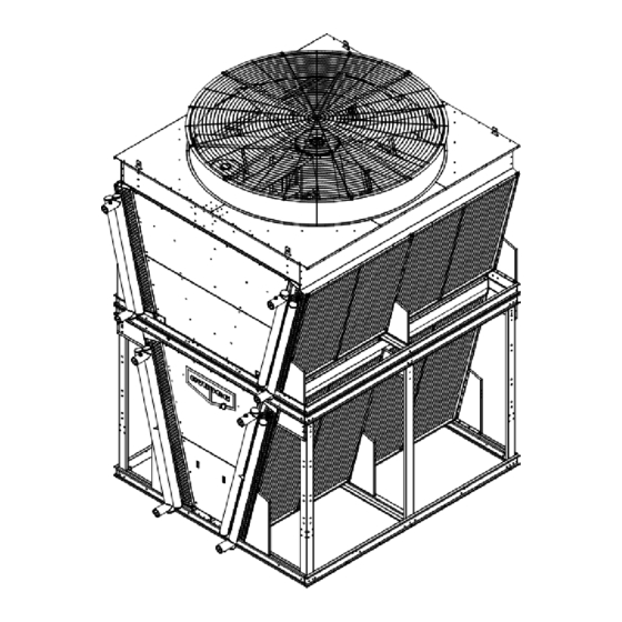
Page 10: V-Coil Configuration Products
. Units with a length less than 19’ (5 .8 m) are provided with standard EVAPCO steel forklift channels positioned under the unit . Forklift channels will be identified by a label on the unit . If labels and forklift channels are not present, STOP! The unit will need to be lifted via a crane . - Page 11 DRY, ADIABATIC AND SPRAY FLUID COOLERS, CONDENSERS & CO GAS COOLERS 30° 30° MAX. MAX. 60° 60° MIN. MIN. Figure 13 – Minimum Crane Lifting Requirements Figure 14 – Rigging Beam Height Requirements Minimum Height (H) Unit Width Dimension 4’ (1.2 m) 2.5’...
-
Page 12: Lifting Requirements - V-Coil Configuration Ec Motor Models
DRY, ADIABATIC AND SPRAY FLUID COOLERS, CONDENSERS & CO GAS COOLERS Lifting Requirements – V-Coil Configuration EC Motor Models Units with EC motor assemblies will have either an A (3’ 10” [1,170 mm]) or J (4’ 3” [1,300 mm]) incremental fin length designator . -
Page 13: Lifting Requirements - V-Coil Configuration Ac Motor Models
Double Stack Configuration Products EVAPCO eco-Air Double Stack units ship in a minimum of two (2) sections. If equipped with adiabatic pad modules or accessories like external service platforms, those components will ship separately and require assembly in the field. -
Page 14: Lower Section Lifting Requirements - Double Stack Base Dry Units
DRY, ADIABATIC AND SPRAY FLUID COOLERS, CONDENSERS & CO GAS COOLERS 1 1/2 CLEARANCE HOLE FOR LIFTING (TYP.) Lower Section Lifting Requirements - Double Stack Base Dry Units Use lifting ears on top of the lower section . An adjustable/spreader lifting beam is required to be used along the entire unit length . -
Page 15: Upper Section Lifting Requirements - Double Stack Base Dry Units
DRY, ADIABATIC AND SPRAY FLUID COOLERS, CONDENSERS & CO GAS COOLERS Upper Section Lifting Requirements - Double Stack Base Dry Units Use lifting ears on top of the upper section as shown in Figure 21 . An adjustable/spreader lifting beam is required to be used along the entire unit length . -
Page 16: Joining Upper And Lower Sections - Double Stack Base Dry Units
DRY, ADIABATIC AND SPRAY FLUID COOLERS, CONDENSERS & CO GAS COOLERS Joining Upper and Lower Sections - Double Stack Base Dry Units Lift upper section onto lower section carefully, using drift pins in the four corners and as needed to align rigging holes in the mating double break flanges . -
Page 17: Installing Lower Section Adiabatic Modules
DRY, ADIABATIC AND SPRAY FLUID COOLERS, CONDENSERS & CO GAS COOLERS INSTALLING LOWER SECTION ADIABATIC MODULES Once the base dry unit is rigged, remove the adiabatic modules and associated components from the lower section crate . Install lower adiabatic module supports (Qty . (8) per 1-cell unit, (16) per 2-cell unit & (24) per 3-cell unit respectively) on the lower section as shown –... - Page 18 DRY, ADIABATIC AND SPRAY FLUID COOLERS, CONDENSERS & CO GAS COOLERS 3 . Once the lower frame module has been installed, place the drain pan in the module, taking care to ensure that the end of the drain pan (1) is flush or inside the end of the lower frame module (2) as shown in Detail A below to allow placement of the lower adiabatic module(s) in the following steps RETURN END DETAIL A...
-
Page 19: Installing Upper Section Adiabatic Modules
DRY, ADIABATIC AND SPRAY FLUID COOLERS, CONDENSERS & CO GAS COOLERS INSTALLING UPPER SECTION ADIABATIC MODULES Once all adiabatic modules on both sides of the lower section are in position, install brackets for the upper modules . See Detail A below for location of bracket installation . INSTALL UPPER ADIABATIC MODULE MOUNTING BRACKET USE M8 HARDWARE DETAIL A... -
Page 20: Adiabatic Water Distribution System Field Assembly Instructions
DRY, ADIABATIC AND SPRAY FLUID COOLERS, CONDENSERS & CO GAS COOLERS 3 . Follow this step only for 2-cell or 3-cell units . 2-cell unit shown below . For 3-cell units, the below step will need to be followed twice on each side . Install the connector piece first, as shown in Detail A, followed by the trim components on the upper and lower section as shown in Figure 30 . - Page 21 DRY, ADIABATIC AND SPRAY FLUID COOLERS, CONDENSERS & CO GAS COOLERS 2 . Install the longer spray branch first as shown below . The longer spray branch is always located inboard within the distribution system . Install the shorter branch (on 2-cell & 3-cell units) next . Reinstall cover panels when spray branch installation is complete .
- Page 22 DRY, ADIABATIC AND SPRAY FLUID COOLERS, CONDENSERS & CO GAS COOLERS 4 . Install intermediate pipe section to connect factory installed adiabatic water distribution piping on upper and lower sections as shown below . Install spray branch feed pipe sections on either side of the factory installed upper adiabatic water distribution piping as shown in Detail A below .
-
Page 23: External Service Platform Installation Instructions
DRY, ADIABATIC AND SPRAY FLUID COOLERS, CONDENSERS & CO GAS COOLERS External Service Platform Installation Instructions Follow the instructions below to install the optional external service platform with a ladder on the return end of each dry or adiabatic double stack unit . The platform mounting channels are installed on the unit from the factory . Follow the instructions sequentially, starting with Detail A . - Page 24 CONTACT yOUR LOCAL EVAPCO REPRESENTATIVE OR THE LOCAL SERVICE CENTER For EVAPCO Authorized Parts and Service, Contact Your Local EVAPCO Representative or the Local Mr. GoodTower Service Provider ® EVAPCO, Inc. — World Headquarters & Research/Development Center P.O. Box 1300 • Westminster, MD 21158 USA 410-756-2600 p •...
Need help?
Do you have a question about the eco-Air EAW-FD Series and is the answer not in the manual?
Questions and answers