
Related Manuals for Bose L1 1S


Summary of Contents for Bose L1 1S
- Page 1 Model 1S System ® Power Stand, Cylindrical Radiator and B1 and B2 Bass Modules ® US/Canada, European and UK Versions ©2015 Bose Corporation Service Manual Reference Number 353918-SM Rev. 04...
-
Page 2: Table Of Contents
Contents Safety Information ..........................3 Warranty .............................3 Electrostatic Discharge Sensitive (ESDS) Device Handling ............3 Specifications ..........................4-5 Part List Notes ...........................5 Product Description ........................6-9 Packaging Part List, L1 ® Model 1S Power Stand (see Figure 1) ..........10 Figure 1. L1 Model 1S Power Stand Packaging View ...............10 Packaging Part List, L1 Model 1S Line Array (see Figure 2) ............ -
Page 3: Safety Information
THE BOSE PRODUCT, AND SHALL NOT BE REPRODUCED OR USED FOR ANY OTHER PURPOSE. Warranty The Bose L1 Model 1S Power Stand is covered by a limited 2-year transferable warranty. The L1 Model II Cylindrical Radiator and the B1 and B2 bass modules are covered by a ®... -
Page 4: Specifications
Specifications External Dimensions Cylindrical Line Array: Height: 2070 mm ± 30 mm. Width: 89 mm ± 5 mm. Depth: 120 mm ± 5 mm Line Array Extension: Height: 978 mm ± 30 mm. Width: 89 mm ± 5 mm. Depth: 120 mm ± 5 mm Power Stand: Height: 110 mm ±... -
Page 5: Part List Notes
Specifications Power Amplifiers (All measured using AES17 20kHz Filter Line Input 1,2) Acoustic Specifications Description System State Specification Power Handling; IEC-265-5 100 Hours Line Array 125W Bass Module 250W Frequency Response, With system EQ 40Hz to 15kHz +/-3dB System Sensitivity: 1W @ 1M Line Array 87dB... -
Page 6: Product Description
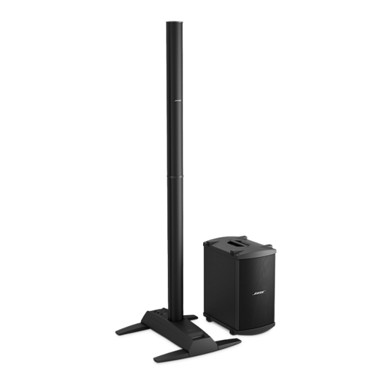
Product Description The L1 ® Model 1S system – with L1 model 1S system with ToneMatch port and B1 bass module Optional equipment ToneMatch port consists of the L1 model ® T1 ToneMatch audio engine 1S power stand, the L1 model 1S Cylindri- cal Radiator loudspeaker, and a B1 or B2 ®... -
Page 7: Model 1S Power Stand (See Figure 1)
Setting up the L1 model 1S power stand ® 1. Holding the power stand vertically on the floor (Figure A), grasp one leg and swing it out as far as it will go. Notice that the other legs swing out automatically. The legs must be fully open before you can plug the L1 Cylindrical Radiator ®... - Page 8 Connecting the B1 or B2 bass module You can place the bass module either B1 or B2 vertically or horizontally on the floor. Normal bass placement is between the legs of the power module stand. 1. Plug one end of the bass module cable into one of the bass module connectors.
- Page 9 Setting the Analog Input Level on the L1 Model 1S Power Stand ® When connecting an audio source to the Analog Input, follow these steps to adjust the input Trim control. 1. Set the Trim control on the power stand to the 0 (zero) position. 2.
- Page 10 Packaging Part List ® Model 1S Power Stand (see Figure 1) Item Description Part Number Qty. Note Number Carton Sheet, 770x340x6 304982 Guide, Owner’s, L1 Model 1S sys (AIM, 3 lang) 356144-0010 Guide, Owner’s, L1 Model 1S sys (EU/UK, 8 lang) 356145-0010 Warranty Card 307430...
- Page 11 Packaging Part List ® Model 1S Line Array (see Figure 2) Item Description Part Number Qty. Note Number Carton Sheet 374346-0010 PE Foam, Side 355204-0010 PE Foam, Middle 355205-0010 Carton 355165-0010 L1.5 Array Extension (Lower Section) Poly Bag, Line Array L1.5 Line Array (Upper Section) Carry Bag, Line Array 354530-0110...
- Page 12 Packaging Part List B1 Bass Module (see Figure 3) Item Description Part Number Note Number CUSHION, PACKING 303838 BAG, POLY, 12 X 16 X 49” BASS MODULE 032494 CARTON 303837 BUBBLE BAG SPEAKER CABLE, 1M 354990-0010 POLYBAG (FOR MANUAL) MANUAL, INSTRUCTION 303154 CARRY BAG 035025...
- Page 13 Packaging Part List B2 Bass Module (see Figure 4) Item Description Part Number Note Number CARTON SHEET, 445 x 578 357536-0010 PE FOAM 355067-0010 POLY BAG, 10” x 14” OWNER’S GUIDE 365143-0010 CABLE, SPKR, BASS MODULE, 1M 354990-0010 B2 CARRY BAG 354529-0110 POLY BAG, 850 x 1000MM B2 BASS MODULE...
- Page 14 Main Part List Upper Housing Assembly to Leg Assembly (see Figure 5) Item Description Part Number Qty. Note Number UPPER HOUSING (PLASTIC HOUSING ONLY) 298051 LEG ASSEMBLY 361795-001S (INCLUDES CAVITY WIRING HARNESS) SCREW, MACHINE, FLAT-CS, M4X12, BZ LABEL, PRODUCT LEG BUMPER, RUBBER Figure 5.
- Page 15 Main Part List ® Model 1S Power Stand Upper Housing (see Figure 6) Item Description Part Number Qty. Note Number HOUSING, UPPER (PLASTIC HOUSING ONLY) 298051 SWITCH, AC POWER, ROCKER, 2P1T 304984 SCREW, M3X12, CSH, BK SCREW, M3X12, CSH, BK SCREW, B-TITE, FLAT-CS, M3X10, BZ I/O PANEL COVER, US/CAN 354557-0110...
- Page 16 Figure 6. Power Stand Upper Housing Exploded View...
- Page 17 Main Part List ® Model 1S Power Stand Cavity and Leg Assembly (see Figure 7) Item Description Part Number Qty. Note Number LEG ASSEMBLY, INCLUDES: 361795-001S LEG-1 FOOT WASHER, METAL, M4X0.8X10 SCREW, M4X12, PH, BK LEG-2 LOWER LEG BEARING SCREW, MACHINE, FLAT-CS, M3X6, BZ SCREW, MACHINE, 4*6, 6.8MM, BK, CR HD SCREW, MACHINE, FLAT-CS, M4X12, BZ BOTTOM COVER...
- Page 18 Figure 7. Power Stand Cavity and Leg Assembly Exploded View...
- Page 19 GRILLE ASSY, UPPPER 304988 (INCLUDES GRILLE, LOGO AND GASKETS) SCREW, TTP/B, M4x9.5mm, BLK RUBBER PAD, D8x1.5mm FOAM, TOP BAFFLE BOSE LOGO 303709 GASKET, END CAP #1, 83x82x1.5mm COVER, END CAP #2 SCREW, B-TITE, FLAT-CS, M3x10mm COVER, END CAP #1 WIRING HARNESS, UPPER ARRAY ASSY...
- Page 20 Main Part List Model 1S Lower Line Array Extension (see Figure 9) ® Item Description Part Number Qty. Note Number SCREW, B-TITE, FLAT-CS, M3x10 MS SCREW, M3x12, CSH, BLK COVER, END CAP #3 HOUSING, EXTENSION, EXTRUDED WIRING HARNESS, EXTENSION BRACKET, END CAP #4 298029 GASKET, LOWER COLLAR FRAME, LOWER COLLAR...
- Page 21 Main Part List ® Model 1S Line Array End Cap Assemblies (see Figure 10) ® Item Description Bose Vendor Part Qty. Note Number Part Number Number END CAP #1 ASSEMBLY 304133 SVC-L211- ENDCAP1 MS SCREW, M3X12, CSH.BK 2901-3012+3000 SCREW, B-TITE, FLAT-CS, M3X10...
- Page 22 END CAP # 1 ASSY END CAP # 2 ASSY END CAP # 3 ASSY DRIVER BAFFLE ASSY END CAP # 4 ASSY Figure 10. L1 Model 1S Line Array End Cap Assemblies Exploded View ®...
- Page 23 Main Part List B1 Bass Module Exploded View (see Figure 11) Item Description Part Number Note Number Screw, M4 X 28, BK, B1 Grille 275465 Woofer Assembly 263998 Gasket, Woofer Assembly 263998 Screw, M4 X 17, BK, B1 Driver 275466 Grille Assembly (includes items 6 and 7 below) 263992 Gasket, Grille Assembly...
- Page 24 Main Part List B2 Bass Module Exploded View (see Figure 12) Item Description Part Number Note Number PANEL ASSY,B2,TERMINAL,SVC 355074-011S (INCLUDES ITEMS 1 TO 6 BELOW) ME SCREW, M4x17, BK-ZN 275466 SWITCH, ROCKER, SPDT 355932-0010 MS SCREW, M3x12, CSH, BLK 275467 SPEAKON NEUTRIK CONNECTOR, 4 WIRE 318841-0000...
-
Page 25: Electrical Part Lists
Electrical Part List Input/Output and DSP PCB Assembly Resistors Reference Description Vendor Part Note Designator Number FERRITE-CORE, 0603, 2.5K, 50MA, 100MHZ, 1808-0906 HZ0603A252R FERRITE-CORE, 0603, 2.5K, 50MA, 100MHZ, 1808-0906 HZ0603A252R R100 100K, RMG, 1/16W, 1%, 0603 4723-104A R101 100K, RMG, 1/16W, 1%, 0603 4723-104A R102 10K, RMG, 1/16W, 1%, 0603/1608... - Page 26 Electrical Part List Input/Output and DSP PCB Assembly Resistors (continued) Reference Description Vendor Part Note Designator Number R150 0R, RMG, 1/16W, 5%, 0603 4723-000J R151 0R, RMG, 1/16W, 5%, 0603 4723-000J R152 0R, RMG, 1/16W, 5%, 0603 4723-000J R153 4.7K, RMG, 1/16W, 1%, 0603/1608 4723-472J R154 4.7K, RMG, 1/16W, 1%, 0603/1608...
- Page 27 Electrical Part List Input/Output and DSP PCB Assembly Resistors (continued) Reference Description Vendor Part Note Designator Number R200 OR, RMG, 1/8W, 5%, 1206 4721-000J R201 4.7K, RMG, 1/16W, 1%, 0603/1608 4723-472A R202 10K, RMG, 1/16W, 5%, 0603/1608 4723-103J R203 1K, RMG, 1/16W, 5%, 0603/1608 4723-102J R204 1K, RMG, 1/16W, 5%, 0603/1608...
- Page 28 Electrical Part List Input/Output and DSP PCB Assembly Resistors (continued) Reference Description Vendor Part Note Designator Number R254 5.6K, RMG, 1/16W, 5%, 0603/1608 4723-562J R255 4.7K, RMG, 1/16W, 1%, 0603/1608 4723-472J R256 10K, RMG, 1/16W, 5%, 0603/1608 4723-103J R257 30.9K, RMG, 1/16W, 1%, 0603/1608 4723-3092 R258 5.6K, RMG, 1/16W, 5%, 0603/1608...
- Page 29 Electrical Part List Input/Output and DSP PCB Assembly Resistors (continued) Reference Description Vendor Part Note Designator Number R301 200K, RMG, 1/16W, 1%, 0603/1608 4723-204A R302 7.5K, RMG, 1/16W, 1%, 0603/1608 4723-752A R303 1K, RMG, 1/16W, 5%, 0603/1608 4723-102J R306 0R, RMG, 1/16W, 5%, 0603 4723-000J R307 0R, RMG, 1/16W, 5%, 0603...
- Page 30 Electrical Part List Input/Output and DSP PCB Assembly Capacitors (continued) Reference Description Vendor Part Note Designator Number C137 10uF, CE, 16V, 20%, SMD, 4X5.4 157D-106MGJ C138 10uF, CE, 16V, 20%, SMD, 4X5.4 157D-106MGJ C139 10uF, CE, 16V, 20%, SMD, 4X5.4 157D-106MGJ C140 10uF, CE, 16V, 20%, SMD, 4X5.4...
- Page 31 Electrical Part List Input/Output and DSP PCB Assembly Capacitors (continued) Reference Description Vendor Part Note Designator Number C205 0.01uF, CC, 50V, 10%, 0603, X7R 150F-103KAC C206 1000pF, CC, 50V, 10%, 0603, X7R 150F-102KAC C207 1000pF, CC, 50V, 10%, 0603, X7R 150F-102KAC C208 1000pF, CC, 50V, 10%, 0603, X7R...
- Page 32 Electrical Part List Input/Output and DSP PCB Assembly Capacitors (continued) Reference Description Vendor Part Note Designator Number C256 470pF, CTC, 0/60, 5%, 0603 15CH-471JAC C257 470pF, CTC, 0/60, 5%, 0603 15CH-471JAC C258 0.015uF, CC, 50V, 10%, 0603, X7R 150F-153KAC C259 0.015uF, CC, 50V, 10%, 0603, X7R 150F-153KAC C260...
- Page 33 Electrical Part List Input/Output and DSP PCB Assembly Capacitors (continued) Reference Description Vendor Part Note Designator Number C307 1000pF, CC, 50V, 10%, 0603, X7R 150F-102KAC C308 1000pF, CC, 50V, 10%, 0603, X7R 150F-102KAC C309 1000pF, CC, 50V, 10%, 0603, X7R 150F-102KAC C310 1000pF, CC, 50V, 10%, 0603, X7R...
- Page 34 Electrical Part List Input/Output and DSP PCB Assembly Capacitors (continued) Reference Description Vendor Part Note Designator Number C356 1000pF, CC, 50V, 10%, 0603, X7R 150F-102KAC C357 10uF, CT, 16V, 20%, SMD, 1.6X3.2 154D-106MCF C358 1000pF, CC, 50V, 10%, 0603, X7R 150F-102KAC C359 1000pF, CC, 50V, 10%, 0603, X7R...
-
Page 35: Input/Output And Dsp Pcb Assembly
Electrical Part List Input/Output and DSP PCB Assembly Inductors Reference Description Vendor Part Note Designator Number L100 FERRITE, CHIP, 0603, BLM18AG102SN1D, 1808-0878 MURATA L101 FERRITE BEAD, SMD, ACB453215, 125 OHM 1802-0630 L102 FERRITE BEAD, SMD, ACB453215, 125 OHM 1802-0630 L104 FERRITE BEAD, SMD, ACB453215, 125 OHM 1802-0630 L105... - Page 36 Electrical Part List Input/Output and DSP PCB Assembly Diodes (continued) Reference Description Vendor Part Note Designator Number D123 LED, SMD, 3.2X2.4X2.4, RD 3700-7840 D124 LED, SMD, 3.2X2.4X2.4, RD 3700-7840 D125 LED, SMD, 3.2X2.4X2.4, RD 3700-7840 D126 LED, SMD, 3.2X2.4X2.4, RD 3700-7840 Transistors Reference...
- Page 37 FOR DSP COVER, SHIELD, BSPAPS2 4135-6841 FOR J102 BRACKET, POWER STAND, 4P, SPK SOCKET 4135-3801 J100 JACK, PHONE, 5P, 6.4MM, BLACK, W/SW 2113-3269 ® (BOSE PART NUMBER – 741427-001S) J101 JACK, PHONE, 5P, 6.4MM, BLACK 2113-3270 J102 SPEAKON ® NEUTRIK ®...
- Page 38 Electrical Part List Input/Output and DSP PCB Assembly Miscellaneous (continued) Reference Description Vendor Part Note Designator Number T100 CHOKE, COMMON MODE, 2200R, AT, 1806-3966 3, 4 100MHZ, 25%, 200MA, SMD T101 CHOKE, COMMON MODE, 2200R, AT, 1806-3966 3, 4 100MHZ, 25%, 200MA, SMD T103 PULSE TRANSFORMER, 225uH, 0.35 OHM, 1806-3670...
-
Page 39: Smps / Power Amplifier Pcb Assembly
Electrical Part List SMPS / Power Amplifier PCB Assembly Resistors Reference Description Vendor Part Note Designator Number 1K, RMG, 1/16W, 1%, 0603/1608 4723-102A 1K, RMG, 1/16W, 1%, 0603/1608 4723-102A 10K, RMG, 1/16W, 1%, 0603/1608 4723-103A 1K, RMG, 1/16W, 1%, 0603/1608 4723-102A 4.7K, RMG, 1/16W, 1%, 0603/1608 4723-472A... - Page 40 Electrical Part List SMPS / Power Amplifier PCB Assembly Resistors (continued) Reference Description Vendor Part Note Designator Number 1K, RMG, 1/16W, 1%, 0603/1608 4723-102A 1K, RMG, 1/16W, 1%, 0603/1608 4723-102A 47K, RMG, 1/16W, 1%, 0603/1608 4723-473A 2.2K, RMG, 1/16W, 1%, 0603/1608 4723-222A 47K, RMG, 1/16W, 1%, 0603/1608 4723-473A...
- Page 41 Electrical Part List SMPS / Power Amplifier PCB Assembly Resistors (continued) Reference Description Vendor Part Note Designator Number R203 470R, RMG, 1/16W, 5%, 0603/1608 4723-471J R204 22R, RMG, 1/10W, 5%, 0805 4720-220J R205 22R, RMG, 1/10W, 5%, 0805 4720-220J R206 0.12R, RMG, 1/4W, 5%, 1206 4725-R12J R207...
- Page 42 Electrical Part List SMPS / Power Amplifier PCB Assembly Capacitors (continued) Reference Description Vendor Part Note Designator Number 4.7uF, CC, 16V, 20%, 1206, SMD, Y5V 150D-475ZCF 0.47uF, CM, 100V, 10%, RBT, 9.5X7.2 153H-474KRN 0.33uF, CM, 100V, 5%, RBT, 7.2 X9.5, 153H- METALLIZED, FARATRON 334JNRM4...
- Page 43 Electrical Part List SMPS / Power Amplifier PCB Assembly Capacitors (continued) Reference Description Vendor Part Note Designator Number 1000pF, CTC, 0/30, 5%, 0805, 1.2x2.5 15CG-102JBD 2200pF, CC, 100V, 5%, 0805, X7R 150H-222JBD 2200pF, CC, 100V, 5%, 0805, X7R 150H-222JBD 0.1uF, CC, 50V, 10%, 0603, X7R 150F-104KAC C100 0.33uF, CM, 300V, 10%, RB, P15, 18X15.5X10...
- Page 44 Electrical Part List SMPS / Power Amplifier PCB Assembly Capacitors (continued) Reference Description Vendor Part Note Designator Number C218 4700pF, CC, 250VAC, 10%, SMD, X7R 150R-472KKIM 3, 4 C219 1uF, CC, 50V, 10%, 1206, X7R, MURATA 150F-105KCFM C220 1uF, CC, 10V, 20%, 0603, 332181050R1 150C-105ZAC C221 1uF, CC, 10V, 20%, 0603, 332181050R1...
- Page 45 Electrical Part List SMPS / Power Amplifier PCB Assembly Diodes (continued) Reference Description Vendor Part Note Designator Number BAS321, 200V, 250MA, 50NS, SOD323 480S-3210 BAS321, 200V, 250MA, 50NS, SOD323 480S-3210 BAS321, 200V, 250MA, 50NS, SOD323 480S-3210 BAS321, 200V, 250MA, 50NS, SOD323 480S-3210 BAS321, 200V, 250MA, 50NS, SOD323 480S-3210...
- Page 46 HALF BRIDGE DRIVER, LV4970M, SO-16 3132-3051 ANALOG 2CH CONTROLLER, LV4930M, 3132-3061 QUAD44 MC33078DR2G, OP-AMP, SO-8 3132-2711 IC200 L6571BD013TR, HALF BRIDGE DRIVER, SO8 3132-3071 (BOSE® PART NUMBER 291328 Miscellaneous Reference Description Vendor Part Note Designator Number CON300 WAFER, 3P, P7, .92/11.88, STRAIGHT...
-
Page 47: Ac Primary Pcb Assembly
Electrical Part List SMPS / Power Amplifier PCB Assembly Miscellaneous (continued) Reference Description Vendor Part Note Designator Number N101 THERMISTER, NTC 5 0HM, 4A, NIOSP005L, 5202-0010 UL/CSA/VDE N200 THERMISTOR, PTC, 1K, 0805, 90 DEG, EPCOS 5202-0011 N201 THERMISTOR, PTC, 1K, 130 DEG, 0805, 5202-0021 EPCOS S100... -
Page 48: Disassembly Procedures
Disassembly Procedures Model 1S Power Stand Procedures ® 1. Leg Assembly Removal 1.1 On a soft surface, place the power stand upside down on its top housing with the legs facing upward. 1.2 With the power stand legs closed, remove the four screws indicated at right. - Page 49 Disassembly Procedures 2.4 Remove the six screws that secure the Input / Output Panel assembly to the power stand upper housing. 2.5 Lift out the Input / Output Panel assem- bly. 3. AC Input PCB Removal 3.1 Perform procedure 1. 3.2 Unplug the wire harnesses at CON300L and CON300B on the AC Input PCB.
- Page 50 Disassembly Procedures 4.4 Remove the screws that secure the bass module output jack and the ToneMatch jack to the input / output panel. 4.5 Remove the nut that secures the analog input jack to the input / output panel. 4.6 Remove the Trim knob. 4.7 Remove the six screws that secure the DSP board to the back of the input / output panel.
- Page 51 1.3 Grasp the edge of the grille (6) and gently lift it away from the enclosure. 2. Bose Logo Removal ® 2.1 Perform procedure 1. 2.2 On the back of the grille (6), unbend the legs of the logo (10). Lift off the Bose logo.
- Page 52 Disassembly Procedures 3. Array Extension Front Cover Removal 1 x5 2 x6 3.1 Remove the four screws (1,2) that secure the end cap # 3 (top end cap) assem- bly to the line array enclosure (4). Lift off the end cap. Do not unplug the molex connector from the speaker harness.
- Page 53 1.1 Remove the four allen screws (1) that secure the grille (5) to the upper and lower speaker end caps. Lift off the grille. 4 8x 2. Bose Logo Removal ® 2.1 Perform procedure 1. 2.2 On the back of the grille (5),...
- Page 54 4x 1 screws (8) that secure the grille (10) to the upper and 2x 3 lower speaker end caps. Lift off the grille. 2. Bose Logo Removal ® 2.1 Perform procedure 1. 4x 8 2x 9 2.2 On the back of the grille (10), remove the gasket, washer, spring and clip (12,13,14,15) from the post of the logo (11).
-
Page 55: Test Procedures
Test Procedures Model 1S Power Stand Tests ® 2.2 Set the power stand trim knob to mid- point. Using a shorted TRS plug, short the analog input jack on the power stand input Equipment Required panel. • dB Meter 2.3 Measure the output noise level at the •... -
Page 56: Hi-Pot Test
There cal abnormalities. is a PDF file located on the L1 Model 1S product specific page on the Bose Service 6. ToneMatch (M) Port Test web site that details how to perform this test. -
Page 57: Ground Bond Test
Test Procedures 2. Ground Bond Test L1 Model 1S Line Array Tests IMPORTANT: This test MUST be performed Set up the unit under test as shown below. if the ground connection from the AC inlet to the chassis has been disturbed as part of a repair. - Page 58 Test Procedures 2.4 Listen carefully for any extraneous Bass Module Tests noises such as rubbing, scraping or ticking. Set up the unit under test as shown below. Note: To distinguish between normal sus- pension noise and rubs or ticks, displace the Audio Signal Audio Signal cone slightly with your fingers.
- Page 59 Test Procedures Note: To distinguish between normal sus- B2 Bass Module Tests pension noise and rubs or ticks, displace the cone slightly with your fingers. If the noise 1. Air Leak Test stays the same, it is normal suspension noise and the driver is good. Suspension 1.1 Set up the bass module as shown on the noise will not be heard with program mate- previous page.
- Page 60 Test Procedures 3. Transducer Phase Test 5. Input Panel EQ Switch Test 3.1 Apply a DC voltage of 20V, positive 5.1 Insert a Neutrik connector which can applied to the positive tab of the dual access pin 2+ and 2- of the connector. Verify banana jack on the bass module test cable the correct resistance (+/-5%) for each bass and negative applied to negative (gnd) tab.
-
Page 61: Appendix
Appendix Model 1S Power Stand Test Cables ® Note: In order to be able to properly test the L1 Model 1S Power Stand, you will need to make a few test cables. 1. Powerstand Boot Test Cable This test cable plugs into the boot connector of the L1 Model 1S Power Stand for all line array amplifier tests. - Page 62 Appendix 3. Bass Module Output Test Cable: This cable is used to connect the Bass Module output jack to the load resistors used in the test procedures. Parts needed: 1- Neutrik Speakon NL4FX X-Line/4 Pole connector. ® ® 4 - Dual banana jacks 2 - 10k ohm, 1/4 Watt resistors 16 or 18 AWG twisted pair wire, 6 feet 18 AWG twisted pair wire, 2 feet...
- Page 63 Appendix 4. L1 ® Model 1S Line Array Test Cables These two cables will allow you to test the upper line array section without an L1 Model 1S power stand. Use these cables for the line array test procedures in this service manual. Line Array Test Cable Parts needed: 1 - 4 pin Molex male connector, Molex part number 39-01-2041...
- Page 64 If you would like to update the T1’s firmware, presets and themes as well during this process, refer to the Bose L1 updater instructions as found on the Bose Live Music Technology Group website at http://www.bose.com/musicians.
-
Page 65: Service Manual Revision History
Service Manual Revision History Date Revision Description of Change Change Driven Pages Level Affected 9/12 Document released at revision 00. Service manual release 3/13 B2 bass module test procedures added New product 59 - 60 5/14 Removed part number for two Service part smps/amplifier boards mounted to heatsink. - Page 66 SPECIFICATIONS AND FEATURES SUBJECT TO CHANGE WITHOUT NOTICE Bose Corporation The Mountain Framingham Massachusetts USA 01701 P/N: 353918-SM Rev. 04 4/2015 (P) http://serviceops.bose.com...
Need help?
Do you have a question about the L1 1S and is the answer not in the manual?
Questions and answers