
Related Manuals for Panasonic FY-3009G1


Summary of Contents for Panasonic FY-3009G1
- Page 1 Service Manual Air Curtain Model NO. FY-3009G1 FY-3012G1 FY-3015G1 Remote control series FY-4009G1 FY-4012G1 FY-4015G1 FY-3009D1 FY-3012D1 FY-3015D1 Sensor series FY-4009D1 FY-4012D1 FY-4015D1 Panasonic Ecology Systems Guangdong Co.Ltd Beijing Branch...
- Page 20 Exploded drawing for remote control series 13 12 Exploded drawing for packing of remote control series...
-
Page 21: Parts Name
Part list for remote control series PARTS NAME FY-3009G1 FY-3012G1 FY-3015G1 FRONT PANEL ACU10001 ACU10002 ACU10003 IMPELLER (L) ACU10004 ACU10005 ACU10006 IMPELLER (R) ACU10007 ACU10008 ACU10009 LOUVER ASSY (L) ACU10010 ACU10011 ACU10012 LOUVER ASSY (R) ACU10013 ACU10014 ACU10015 PLATE FEC050H018E... - Page 22 Part list for remote control series PARTS NAME FY-4009G1 FY-4012G1 FY-4015G1 FRONT PANEL ACU10001 ACU10002 ACU10003 IMPELLER (L) ACU10004 ACU10005 ACU10006 IMPELLER (R) ACU10007 ACU10008 ACU10009 LOUVER ASSY (L) ACU10010 ACU10011 ACU10012 LOUVER ASSY (R) ACU10013 ACU10014 ACU10015 PLATE FEC050H018E FEC050H018E FEC050H018E MOTOR...
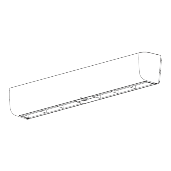
- Page 23 Exploded drawing for sensor series Exploded drawing for packing of sensor series...
- Page 24 Part list for sensor series PARTA NAME FY-3009D1 FY-3012D1 FY-3015D1 FRONT PANEL ACU10001 ACU10002 ACU10003 IMPELLER (L) ACU10004 ACU10005 ACU10006 IMPELLER (R) ACU10007 ACU10008 ACU10009 LOUVER ASSY (L) ACU10010 ACU10011 ACU10012 LOUVER ASSY (R) ACU10013 ACU10014 ACU10015 PLATE FEC050H018E FEC050H018E FEC050H018E MOTOR ACU10019...
- Page 25 Part list for sensor series PARTS NAME FY-4009D1 FY-4012D1 FY-4015D1 FRONT PANEL ACU10001 ACU10002 ACU10003 IMPELLER (L) ACU10004 ACU10005 ACU10006 IMPELLER (R) ACU10007 ACU10008 ACU10009 LOUVER ASSY (L) ACU10010 ACU10011 ACU10012 LOUVER ASSY (R) ACU10013 ACU10014 ACU10015 PLATE FEC050H018E FEC050H018E FEC050H018E MOTOR ACU10022...
- Page 26 Routine maintenance for basic series ◆Name plate is affixed on right side of unit, indicating model No. and product No.. ◆ Safety precaution: • Make sure to disconnect the power source before maintenance. • Don’t impair the related part in maintenance. •Initial operation after maintenance shall be done while few people around because large amount of dust could be caused .
- Page 27 Trouble shooting guide for basic series ◆ Safety precaution: • make sure to disconnect the power source before maintenance. • don’t damage the related part in maintenance • wear the protection equipment in maintenance Replace the front cover ◆ pull out the cap as shown in figure above before releasing the ◆...
- Page 28 Trouble shooting guide for basic series ◆ you can replace the ◆ release the screw as ◆open the cover of push- push-button switch. button switch. indicated above Caution : • don’t impair the cord while replacing the push-button switch • firmly connect the connector after replacement •...
- Page 29 Trouble shooting guide for basic series ◆ loosen the jbckscrew used for fixing ◆ replace the impeller after removing impeller with cross screwdriver (only loosen) Caution for replacing the impeller: LEFT RIGHT • replace the right impeller with same method •...
- Page 30 Trouble shooting guide for basic series ◆ then you can replace the shaft after ◆ remove the metal plate removing. Replace the capacitor ◆ then you can replace the capacitor after ◆ release the screws. removing. Replace the motor ◆ release the screws used for fixing the ◆...
- Page 31 Trouble shooting guide for basic series ◆ release the screws fixed on side plate near ◆ remove the side plate to motor ◆ release the screws used for fixing the ◆ move to left side and remove the motor motor bracket. assembly Caution for replacing the motor:...
- Page 32 Trouble shooting guide for remote controlseries Note: • maintenance step for remote control series is same as basic series. • structure difference between them :compared to basic series, remote control is added two PCB board (power board and control board )without push-button switch special description is given to introduce the steps for replacing the two PCB boards below, further more steps please refer the steps for basic series.
- Page 33 Trouble shooting guide for sensor series Note: ◆maintenance step for sensor series is same as basic series. ◆ structure difference between them : compared to basic series, sensor series is added a power board(same as remote control series ) , maintenance step is given in the following: •...
Need help?
Do you have a question about the FY-3009G1 and is the answer not in the manual?
Questions and answers