Sign In
Upload
Download
Table of Contents
Contents
Add to my manuals
Delete from my manuals
Share
URL of this page:
HTML Link:
Bookmark this page
Add
Manual will be automatically added to "My Manuals"
Print this page
×
Bookmark added
×
Added to my manuals
Manuals
Brands
FMC Manuals
Water Pump
M08
Owner's manual
FMC M08 Owner's Manual
Industrial pump
Hide thumbs
1
2
Table Of Contents
3
4
5
6
7
8
9
10
11
12
13
14
15
16
17
18
19
20
21
22
23
24
25
26
27
28
29
30
31
32
33
34
35
36
page
of
36
Go
/
36
Contents
Table of Contents
Troubleshooting
Bookmarks
Table of Contents
Table of Contents
Storage before Installation
Selecting Pump Location
Securing Pump to Foundation
Check Points before Starting
Starting the Pump
Priming the Pump
Shutdown During Freezing Temperatures
Maintenance Procedures
Service
Troubleshooting Chart
Ordering Parts
Advertisement
Quick Links
1
Maintenance Procedures
2
Ordering Parts
Download this manual
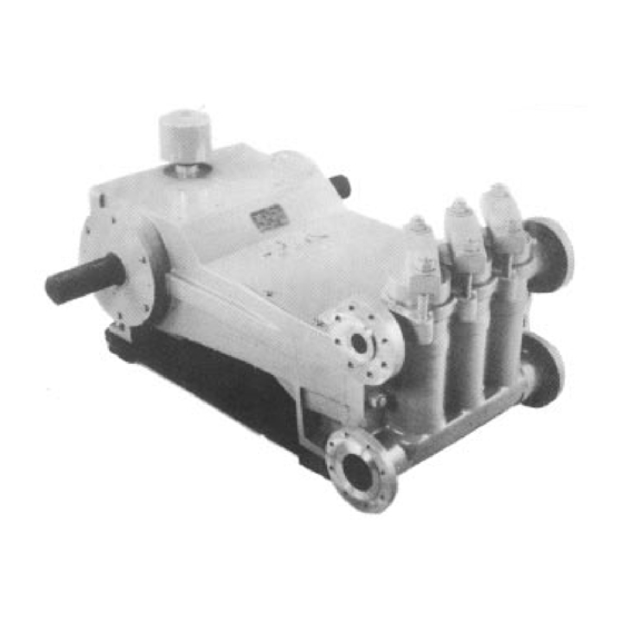
Owners Manual
Industrial Pump
Models M08, M12, M16
Manual No.5268857
Table of
Contents
Previous
Page
Next
Page
1
2
3
4
5
Advertisement
Table of Contents
Need help?
Do you have a question about the M08 and is the answer not in the manual?
Ask a question
Questions and answers
Subscribe to Our Youtube Channel
Related Manuals for FMC M08
Water Pump FMC M28 Manual
(42 pages)
Water Pump FMC M12-HD Operation & Maintenance Manual
Piston pump (20 pages)
Water Pump FMC M12 Owner's Manual
Industrial pump (36 pages)
Water Pump FMC Ao4 Operation And Maintenance Manual
(47 pages)
This manual is also suitable for:
M12
M16
Table of Contents
Print
Rename the bookmark
Delete bookmark?
Delete from my manuals?
Login
Sign In
OR
Sign in with Facebook
Sign in with Google
Upload manual
Upload from disk
Upload from URL


Need help?
Do you have a question about the M08 and is the answer not in the manual?
Questions and answers