
Related Manuals for Prins VALVECARE-DI


Summary of Contents for Prins VALVECARE-DI
- Page 1 VALVECARE-DI SYSTEM MANUAL SYSTEM VERSION ValveCare-DI DATE 10-03-2022 Revision version v 1.8 Copyright © Prins Autogassystemen 2022...
-
Page 2: Table Of Contents
Mirror leaflet ..........................8 Nipples and hose connections ....................9 8.7.1 Set part numbers ........................10 DETAILED PRINS LPG SYSTEM INTEGRATION ................11 Tool requirements ........................11 Installation flow ........................11 Wiring diagram VSI-3 DI / AFC-3.0 DI ..................12 Wiring diagram VSI-2.0 DI / AFC-2 .................. -
Page 3: Manual Updates / Revision
➢ ValveProtector program description ➢ Assembly of ValveCare-DI device with non-original parts, which have not been checked and recommended by Prins, is not allowed and may cause material damages for which Prins cannot be held liable. This manual was developed by Prins Autogassystemen B.V. -
Page 4: General Instructions
➢ For maintenance instructions and filter registration also see the Driver’s Guide. ➢ Prins Autogassystemen is not responsible for any damages to people or objects because of changes to Prins products. ➢ Power and fuses: ⬧... -
Page 5: Safety Instructions
Safety instructions ➢ Always avoid direct contact between additive and skin, eyes or mouth. Always wear protective clothing and safety goggles during work or maintenance on the ValveCare-DI dosing system. ➢ If the additive encounters the eyes, this may cause irritation. In this case rinse the eyes 10 to 15 minutes with water and seek medical attention. -
Page 6: Introduction
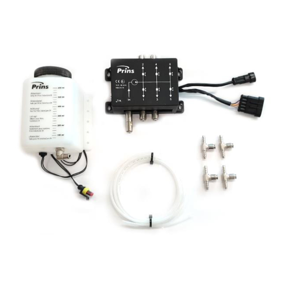
General manual ValveCare-DI Introduction The ValveCare-DI system is a full electronic sequential regulated additive dosing system suitable for direct injected and port gas injected engines. It can be applied to VSI-2.0 (MPI), VSI-2.0 DI, VSI-3 DI and Direct LiquiMax. In combination with the highly effective Prins additive, the system will contribute to a cleaner combustion chamber and improved durability of valves and valve-seats against excessive wear. - Page 7 After 100l gas the injected additive should be 100ml. Empty reservoir In case the additive reservoir is empty, the Prins switch will indicate a blue exclamation mark (blinking), and the engine can run another 4 hours on LPG. After 4 hours the engine only runs on petrol and the exclamation mark and will be active. Refilling the additive-reservoir will make driving on LPG possible again.
-
Page 8: Additive Reservoir
The wiring loom has 3 super seal connectors. A power supply connector, an in/output connector and a connector for the additive reservoir level. The loose wires should be soldered to the Prins wiring loom, vehicle wiring or added into an AFC connector. - Page 9 The consumption of the additive has a ratio of 1 litre additive on 1000 litre LPG. After 100l gas the injected additive should be 100ml. Only use Prins ValveCare-DI fluid. Warranty will be void if any other liquid is used. Part number ➢...
- Page 10 Cut the PTFE (white) and Nylon (black) hose with a sharp knife or hose cutter in a perfect 90-degree angle. This is necessary for a proper fitting in the coupling and prevents any Remark! damages to the internal coupling seals. Copyright © Prins Autogassystemen B.V. 2022...
- Page 11 3- & 5- cilinder engine In case of a 3- or 5-cylinder engine, outlet 4 and 6 should not be used. In the ValveCare-DI software, the right settings should be made. Prins advises to use a small piece of 4mm PA hose, melted together, to plug of the unused outlet.
-
Page 12: Detailed Prins Lpg System Integration
PAGE 11 General manual ValveCare-DI Detailed Prins LPG system integration Cable diagnostic ValveCare-DI ValveCare-DI software Prins Diagnostic program V2.0 099/040003 Tool kit PDT Diagnose Hose cutter Compressed air & air gun 191/020001 099/520024/A Insulating tape & adhesive Basic workshop Soldering iron & soldering tin... - Page 13 Battery + Orange Solder to Grey A3 TANK VALVE 1 Purple Solder to Grey White yellow H1 G INJ OUT 1 Solder to / Yellow pink Brown Yellow pink J1 SENT IN3 Insert into Copyright © Prins Autogassystemen B.V. 2022...
- Page 14 A3 TANK VALVE 1 Purple Solder to Grey White yellow H1 G INJ OUT 1 Brown Blue Purple F1 AD4 (Lambda) Insert into/ Yellow pink Solder to F2 Brown Yellow pink F2 +5V PULL-UP Copyright © Prins Autogassystemen B.V. 2022...
- Page 15 Solder to Grey white +IGNITION Relay 30 (3) Connect to Battery + Orange Solder to 2 +12V TANK VALVE Purple Solder to 106 G+ INJ 1 Yellow pink Solder to Yellow pink 60 DIG IN3 Copyright © Prins Autogassystemen B.V. 2022...
- Page 16 +IGNITION Relay 30 (3) Connect to Battery + Orange Solder to 2 +12V TANK VALVE Purple Solder to 106 G+ INJ 1 Blue 39 AD8 Yellow pink Solder to Blue 29 PULL UP1 Copyright © Prins Autogassystemen B.V. 2022...
- Page 17 Relay 30 (3) Connect to Battery + Orange Solder to 2 +12V TANK VALVE Purple Solder to 106 G+ INJ 1 19 AD4 Blue Solder to Yellow pink + resistor 1K8 9 +5V Sensor blue Copyright © Prins Autogassystemen B.V. 2022...
- Page 18 Connect to Battery + Orange Solder to L1 +12V TANK VALVE Purple Solder to White yellow G4 INJ OUT 1 B1 AD4 Blue Solder to Yellow pink + resistor 1K8 E1 +5V Sensor blue Copyright © Prins Autogassystemen B.V. 2022...
- Page 19 7 +IGNITION Relay 30 (3) Connect to Battery + Orange Solder to Green yellow 24 +12V FMU SUPPLY Purple Solder to Purple white 8 RPM Yellow pink Solder to Yellow pink 60 DIG IN3 Copyright © Prins Autogassystemen B.V. 2022...
- Page 20 Yellow pink Solder to 29** Blue 29 PULL UP1 ** Tyco AFC connector : module needed : solder wire, Order white wiring module 191/140049 ** Bosch AFC connector : no module needed, insert wire Copyright © Prins Autogassystemen B.V. 2022...
- Page 21 PAGE 20 General manual ValveCare-DI Connector overview VSI-3 DI VSI-2.0 DI VSI-2.0 Direct LiquiMax Copyright © Prins Autogassystemen B.V. 2022...
- Page 22 Solder the 1K8 resistor Remove isolation 1 cm Solder the wires Cut the resistor wires (7mm) Result Shrink the sleeve and solder the resistor wires Add the shrink sleeve onto the wiring loom Copyright © Prins Autogassystemen B.V. 2022...
- Page 23 PAGE 22 General manual ValveCare-DI Application software number 1066 is needed. Check this version before installing the ValveCare-DI system. When the software number does not match, flash the AFC with the latest online firmware. Contact your importer / distributer when the Application software number still does not match.
-
Page 24: Wiring Diagram Vsi-3 Di / Afc-3.0 Di
Two options to modify the ValveCare-DI settings: 1. Manual set the ValveCare-DI parameter. 2. Write the dedicated ValveCare-DI calibration file into the ValveCare-DI module. Available at online firmware in the Prins diagnostic program. (mainly VSI-3 DI calibrations) Manual set the ValveCare-DI parameter VSI-2.0 (DI) &... - Page 25 ‘Set ValveCare-DI parameters’) Expert modes - Other RPM adjust Set to correct engine speed => AFC engine Speed Write the dedicated ValveCare-DI calibration file into the ValveCare-DI module Go to the online firmware in the Prins diagnostic program. Check if a ValveCare-DI calibration is available.
- Page 26 PAGE 25 General manual ValveCare-DI Write (F12) the calibration into the module. Press Read (F11) and check if the Protocol Prins has been modified to Protocol Prins. Configuration → Expert View √ → Output → System shutdown → Protocol Prins Check all settings shown in the table below.
-
Page 27: Valvecare-Di Software (Valve-Protector)
PAGE 26 General manual ValveCare-DI ValveCare-DI software (Valve-Protector) All ValveCare-DI modules purchased from Prins have default Prins settings and a special Prins communication software. Please follow the steps to make the system suitable for the Prins system Download ValveCare-DI configuration tool. - Page 28 PAGE 27 General manual ValveCare-DI Open the Valve Protector software Press F11 to read the ValveCare- DI setting Check the software version Devices -> Informations Prins ValveCare-DI Copyright © Prins Autogassystemen B.V. 2022...
- Page 29 Press F12 [Write] to save the parameters in the memory of the dosing module. Remark: Press F12 [Write] to save the parameters in the memory of the dosing Remark! module. data gets lost when not writing to the memory! Copyright © Prins Autogassystemen B.V. 2022...
- Page 30 ➢ The additive feed line between the reservoir and dosing module needs to be completely filled with the additive. ➢ Air bubbles may exist in the hoses between the ValveCare-DI module and inletmanifold. This is normal. Start the engine and switch over to LPG to...
- Page 31 Clean the components when they are dirty. The additive reservoir can always be re-filled. Only refill with the original blue ValveCare-DI additive. If any other additive is used, Prins can no longer guarantee a proper operation and warranty shall expire directly.
- Page 32 The injection time shown at ‘Live’ need to be below. the same as the injection time shown in the AFC software. Note: Always use Write (F12) to save the (Expert modes – Other) setting into the ValveCare-DI module. VSI-3 DI Ground VSI2.0-DI - AFC-2 Positive VSI-2.0 - AFC-2 Positive VSI-2.0 AFC Compact...
- Page 33 Check if all settings are correct in the ValveCare-DI module. See chapter ‘ValveCare-DI settings’ Note: Always use Write (F12) to save the setting into the ValveCare-DI module. 2) Second: Check and calculate the injector flowrate. Use the calculator to use the default calculated value.
-
Page 34: Valvecare-Di Module
Laptop and the ValveCare-DI module. When there are USB communication issues between a laptop and ValveCare-DI module, you can check to which COM port the ValveCare-DI USB cable is assigned and change it if necessary. The communication icon at the bottom left will flash orange while connecting. - Page 35 Note: When overwriting this, the device that was using this specific COM Port Number, will automatically have a different number assigned to it, so this should not cause any issues with other devices. Copyright © Prins Autogassystemen B.V. 2022...
- Page 36 Possible solutions -1Hz / 0Hz: - Set VC-DI Parameter ‘System Shutdown’ to ‘Protocol Prins’ - Install a Relay for the +12V supply for the ValveCare-DI unit - Check/connect the Diagnostic wire(s) connected to the AFC - Check the AFC PULL-UP calibration setting for VSI-2.0 DI systems...
-
Page 37: Prins Afc Software V2
PAGE 36 General manual ValveCare-DI AFC DTC’s Read out the diagnostic trouble codes with the Prins AFC Software v2. Code Description description 1) An open circuit of the level sensor signal can cause this code. Check for wiring issues and if the 2-pole level sensor connector is fitted correctly. -
Page 38: Infobulletins
312: ValveCare-DI wiring loom (Power relay) This high current (10-12A) can cause problems if the ValveCare-DI power cable is directly connected to a random ignition + cable of the car. To improve the power supply reliability, a power relay is added in combination with a 15 Amp fuse.
Need help?
Do you have a question about the VALVECARE-DI and is the answer not in the manual?
Questions and answers