
Related Manuals for Xyratex RS-1220-F4-5412E

Summary of Contents for Xyratex RS-1220-F4-5412E
- Page 1 RS-1220-F4-5412E & RS-1220-E3-XPN Installation and User Guide Part No. 0090505-04A Issue 4.0 January 30, 2009...
-
Page 2: Acknowledgments
RS-1220-F4-5412E & RS-1220-E3-XPN Installation and User Guide Notices The information in this document is subject to change without notice. While every effort has been made to ensure that all information in this document is accurate, the Authors accept no liability for any errors that may arise. -
Page 3: Table Of Contents
1.5 Rack System Precautions ..........................5 1.6 Data Security ..............................5 1.7 Special Tools and Equipment ........................6 System Overview .............................. 7 2.1 RS-1220-F4-5412E RAID Enclosure ......................7 2.2 RS-1220-E3-XPN Expansion Enclosure ...................... 8 2.3 Enclosure Chassis ............................9 2.3.1 Enclosure Drive Slots ........................ - Page 4 RS-1220-F4-5412E & RS-1220-E3-XPN Installation and User Guide 3.7 Cabling Multiple Enclosures ........................49 3.8 Ethernet Connection ..........................49 3.9 Drive Slot Arrangement ..........................50 3.9.1 Drive Location Rules ........................50 3.9.2 Drive Start ............................50 3.10 AC Power Cord Connection ........................51 3.11 Grounding Checks .............................
- Page 5 Contents 6.3.3 RAID Controller Module ......................... 82 6.3.4 Disk I/O Module ..........................85 6.3.5 Removal and Installation of the Blank Module ................87 6.3.6 Replacing a Battery Module ......................88 6.3.7 Replacing SFP Transceivers ......................89 6.3.8 Replacing a Drive Carrier Module ....................90 6.3.9 Engaging the Anti-tamper Locks ......................
- Page 6 RS-1220-F4-5412E & RS-1220-E3-XPN Installation and User Guide...
-
Page 7: Preface
This user guide assumes that you have a working knowledge of the Fibre Channel Arbitrated Loop (FC- AL) and SAS or SATA environments into which you are installing the RS-1220-F4-5412E RAID and RS-1220-E3-XPN storage solution. If you do not have these skills, or are not confident with the instructions in this guide, request assistance to proceed with the installation. -
Page 8: Revision History
RS-1220-F4-5412E & RS-1220-E3-XPN Installation and User Guide Revision History Version Date Description of Change March, 2007 Initial Release August, 2007 Related document part numbers. Changes were related to rack installation illustrations, Controller LED table, Drive Status LEDs, and OPS LED table. Modified Drive Carrier LEDs table. -
Page 9: Safety Guidelines
Safety Guidelines Chapter 1 Safety Guidelines 1.1 Safe Handling Caution If this equipment is used in a manner not specified by the manufacturer, the protection provided by the equipment may be impaired. In order to comply with applicable safety, emission and thermal requirements, no covers should be removed and all bays must be populated with plug-inmodules. -
Page 10: Safety
RS-1220-F4-5412E & RS-1220-E3-XPN Installation and User Guide 1.2 Safety • RS-1220 enclosures must only be operated from a power supply input voltage range of 100-240 V, 50-60 Hz. Figure 1–2 Power Supply Module Caution Label • The plugs on the power supply cord are used as the main disconnect device. Ensure that the socket outlets are located near the equipment and are easily accessible. - Page 11 Safety Guidelines Figure 1–5 Power Supply Warning Label • The power connection should always be disconnected prior to removal of the power supply module from the enclosure. • A safe electrical ground (earth) connection must be provided to the power cords. Check the grounding of the enclosure before applying power.
-
Page 12: Battery Safety
RS-1220-F4-5412E & RS-1220-E3-XPN Installation and User Guide Figure 1–7 Drive Carrier Module Caution Label • Do not operate with any drive carrier modules missing. • Drive spin down time is approximately 30 seconds. Allow the drives to spin down before removing them. -
Page 13: Class 1 Laser Product
Safety Guidelines 1.4 Class 1 Laser Product The RS-1220-F4-5412E RAID Controllers are supplied with optical SFP Transceiver modules. They contain a laser that complies with Laser Class 1, US 21 CFR (J) & EN 60825-1, UL (NRTL) and TUV. Important... -
Page 14: Data Security
RS-1220-F4-5412E & RS-1220-E3-XPN Installation and User Guide 1.6 Data Security • Power down your host computer and all attached peripheral devices before beginning installation. • Each enclosure contains up to 12 removable disk drive modules. Disk drives are fragile, handle them with care and keep them away from strong magnetic fields. -
Page 15: System Overview
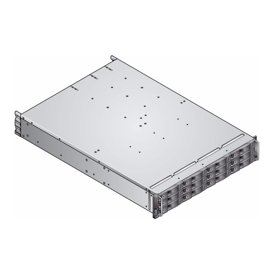
System Overview 2.1 RS-1220-F4-5412E RAID Enclosure The RS-1220-F4-5412E RAID enclosure is a 2U (rack space) disk drive enclosure, housing twelve low profile (1 inch high), 3.5 inch form factor SATA or SAS disk drives and up to two FC-SAS RAID Controllers. -
Page 16: Rs-1220-E3-Xpn Expansion Enclosure
Expanding the number of disk drives up to sixty (60) is achieved by connecting from one to four RS- 1220-E3-XPN expansion enclosures. The enclosures are interconnected using SAS cables from the RS-1220-F4-5412E RAID Controllers to the first RS-1220-E3-XPN expansion enclosure Disk I/O modules. Then the remaining expansion enclosures are connected from one set of Disk I/O modules to the next enclosure’s Disk I/O modules,... -
Page 17: Enclosure Chassis
2.3 Enclosure Chassis The RS-1220 design concept is based on an enclosure subsystem together with a set of plug-in modules. The RS-1220-F4-5412E RAID enclosure as supplied consists of: • Chassis and backplane with integral (front panel mounted) OPS panel (See Figure 2–5). -
Page 18: Enclosure Drive Slots
RS-1220-F4-5412E & RS-1220-E3-XPN Installation and User Guide 2.3.1 Enclosure Drive Slots The chassis assembly contains 12 drive slots located at the front, each of which accommodates the appropriate plug-in drive carrier module. A drive slot is defined as the space required to house a single 1.0"... -
Page 19: Alarms(Audible And Visible)
System Overview 2.3.3 Alarms(Audible and Visible) Table 2–1 OPS Panel LED States OPS Panel LEDs Other Associated State Description LEDs or Alarms Power System Logical Fault Fault Identify (Green/ (Amber) (Amber) (Blue) Amber) Aux present, overall power failed or switched off. Single beep, two OPS Panel power on (5s) test double beep... - Page 20 RS-1220-F4-5412E & RS-1220-E3-XPN Installation and User Guide RS-1220 enclosures include an Audible Alarm which indicates when a fault state is present. The following conditions will activate the Audible Alarm: • Fan Fault or Failure (single or dual) • Voltage Out Of Range •...
-
Page 21: The Plug-In Modules
An RS-1220 enclosure requires the following modules for normal operation: • (2) 350W AC Power Supply modules. • (1) Cooling Fan module. • RS-1220-F4-5412E: (1 or 2) F5412E RAID Controller modules (Blank module required in single controller configurations). OR • RS-1220-E3-XPN: (2) Disk I/O modules. -
Page 22: Cooling Fan Module
RS-1220-F4-5412E & RS-1220-E3-XPN Installation and User Guide When inserting a power supply module into a operating enclosure with data I/O in progress, smoothly Note insert the module into the open bay and secure the latch. Harshly inserting the module could possibly cause drives to temporarily go offline which could affect ongoing data I/O operations. - Page 23 System Overview During the power up sequence, the Cooling Fan Module Fault LED will be illuminated until the RAID Note Controllers have completed their boot up cycle. This also applies to the expansion enclosure except in this case the Disk I/O modules must complete their boot cycle before the LED is extinguished. The system must be operated with low pressure rear exhaust installation (back pressure created by rack Note doors and obstacles not to exceed 5 pascals (0.5mm water gauge)).
-
Page 24: F5412E Raid Controller Module
2.4.3 F5412E RAID Controller Module One or two F5412E RAID Controller modules (according to customer configuration) are supplied mounted in the rear of the enclosure as part of the RS-1220-F4-5412E enclosure core product. Important Do not mix RAID Controller modules and Disk I/O modules in the same enclosure. Disk I/O modules are only installed in the expansion enclosure and RAID Controllers modules are only installed in the RAID enclosure. - Page 25 System Overview Important Only shielded Cat 5 (or better) cables should be used for connection to the Ethernet port for EMC conformance. • A RS232 serial port provides access to the RAID Configuration Utility. The RS232 port is similar in appearance to a USB port, though it is not a USB port. It Note: requires a special cable and users should NOT attach a USB cable to this port.
- Page 26 RS-1220-F4-5412E & RS-1220-E3-XPN Installation and User Guide The following table provides a description of the F5412E RAID Controller module’s LEDs: Table 2–4 F5412E RAID Controller Module LED Descriptions LED/Icon Description Battery Fault This LED appears between the controller’s Ethernet and RS232 ports.
- Page 27 System Overview 2.4.3.1 Battery Module The F5412E RAID Controller module assembly includes a removable battery module, as shown in Figure 2–10 Figure 2–12. The battery pack provides protection of the cache memory contents should the AC power fail. The battery is a replaceable Lithium-ion battery pack. When the controller is powered on, it checks to determine if a battery module is present.
-
Page 28: Disk I/O Module
RS-1220-F4-5412E & RS-1220-E3-XPN Installation and User Guide Typical supported cabling configurations are shown in section 3.6, “Cabling the Enclosures,” on page Important Optical SFP modules must be UL (or other North American NRTL) RECOGNIZED COMPONENT and the laser in the module must comply with Laser Class 1, US 21 CFR (J) and EN 60825-1. - Page 29 System Overview Figure 2–15 Disk I/O Module Front Panel The white diamond icon with an arrow pointing away from the connector indicates an expansion “out” port, and a white circle icon with an arrow pointing towards the connector indicates a host “in” port. Table 2–5 Disk I/O Module LEDs State...
-
Page 30: Drive Carrier Module
RS-1220-F4-5412E & RS-1220-E3-XPN Installation and User Guide 2.4.5 Drive Carrier Module The Drive Carrier module comprise a hard disk mounted in a carrier, and for SATA disk drives a MUX Transition card. Each enclosure drive slot will house a single Low Profile 1.0 inch high, 3.5 inch form factor disk drive in its carrier. - Page 31 System Overview 2.4.5.1 Drive Status LEDs Each drive carrier incorporates two LEDs, an upper (Green) and lower (Amber) LED. In normal operation the green LED will be ON steady and will flash OFF as the drive operates indicating I/O activity. Figure 2–18 Drive Status LEDs The amber LED will only be ON if there is a drive fault.
- Page 32 RS-1220-F4-5412E & RS-1220-E3-XPN Installation and User Guide 2.4.5.3 MUX Transition Cards SATA disk drive carriers are installed with either a Active-Passive (A/P) or Active-Active (A/A) MUX Transition card, sometimes referred to as a dongle. This MUX transition card is located between the drive plane and the disk drive, and is mounted to the rear of the carrier on each SATA disk drive.
- Page 33 System Overview Figure 2–21 Drive Carrier Module with SATA Disk Drive and Active-Passive MUX Transition Card 2.4.5.4 Dummy Carrier Modules Dummy Carrier modules are provided for the unused drive slots. They are designed as integral module front cap and must be installed in all unused drive slots to maintain a balanced airflow. Figure 2–22 Dummy Drive Carrier Module...
-
Page 34: Blank Modules
RS-1220-F4-5412E & RS-1220-E3-XPN Installation and User Guide 2.4.6 Blank Modules When only one RAID Controller module is installed (RS-1220-F4-5412E) or only one Disk I/O module is installed (RS-1220-E3-XPN), a Blank module must be installed in the vacant module bay. This will maintain proper airflow for correct system operation. -
Page 35: Getting Started
Chapter 3 Getting Started 3.1 Introduction In this chapter, you are shown how to install your RS-1220-F4-5412E and RS-1220-E3-XPN enclosure into an industry standard 19-inch rack cabinet and configure the enclosure subsystem. Caution Use only the power cords supplied or those which match the specification quoted in section B.5 on... - Page 36 RS-1220-F4-5412E & RS-1220-E3-XPN Installation and User Guide Table 3–1 Enclosure System Configuration Module Location F5412E RAID Module Two F5412E RAID Controller modules or one F5412E RAID Controller (RS-1220-F4-5412E) module plus one blank module can be installed. The modules are installed...
-
Page 37: Enclosure Drive Slot Numbering Convention
Getting Started 3.2.1 Enclosure Drive Slot Numbering Convention The enclosure’s drive slot numbering convention is shown in Figure 3–1 Figure 3–2, and detailed in section 3.9 on page 50. A drive slot is defined as the space required to house a single 1.0" high 3.5 inch disk drive in its carrier module. -
Page 38: Enclosure Installation Procedures
RS-1220-F4-5412E & RS-1220-E3-XPN Installation and User Guide 3.4 Enclosure Installation Procedures The following procedures describe the installation of an enclosure and highlights any critical co- requisite requirements and good handling practices which we encourage you to follow so as to ensure that a successful installation is achieved in the safest manner. -
Page 39: Rack Installation Pre-Requisites
Getting Started 3.4.3 Rack Installation Pre-Requisites The RS-1220-F4-5412E and RS-1220-E3-XPN enclosures are designed for installation into an industry standard 19-inch cabinet capable of holding the unit. • Minimum depth 700 mm (27.6 inches) from front flange to rear metalwork (excludes rear cabling). - Page 40 RS-1220-F4-5412E & RS-1220-E3-XPN Installation and User Guide Attach the left and right chassis slides to the enclosure sides using a total of six M3x4 button head screws (see Figure 3–4), three each side. The front portion of the chassis slide has two tangs which insert into holes on the forward edge of the side panel.
- Page 41 Getting Started NOTE: Remove nut when using the tapped hole rack posts. Figure 3–5 Securing Brackets to Rack - Left Hand Assembly Shown Mount the enclosure in the rack as follows (refer to Figure 3–6): Using an assistant, lift the enclosure aligning it with the rack rails and carefully insert the chassis slides into the rack rails.
- Page 42 RS-1220-F4-5412E & RS-1220-E3-XPN Installation and User Guide Tighten the front rack bracket mounting screws, again, previously left loose. Push the enclosure completely into the rack cabinet and attach to the front of the rack using the captive fasteners on the front flanges (located just outside of the handles).
-
Page 43: Module Removal & Installation
Getting Started 3.5 Module Removal & Installation The RS-1220-F4-5412E and RS-1220-E3-XPN enclosure is supplied fully populated with all plug-in modules installed. However, during installation it is strongly recommended to remove the plug-in modules in order to lighten the enclosure while the rail assemblies are installed and the enclosure installed into the rack cabinet. -
Page 44: Cooling Fan Module
RS-1220-F4-5412E & RS-1220-E3-XPN Installation and User Guide Slide the module into the enclosure (Figure 3–8). Figure 3–8 Inserting the Power Supply Module Continue to push the module until it fully seats. A click should be heard as the handle latch engages. - Page 45 Getting Started Figure 3–10 Removing the Cooling Fan Module 3.5.2.2 Installing the Cooling Fan Module Check for damage, especially to the rear connector on the module. Caution Handle the module carefully and avoid damaging the connector pins. Do not install the module if any pins appear to be bent.
-
Page 46: Raid Controller Module
RS-1220-F4-5412E & RS-1220-E3-XPN Installation and User Guide 3.5.3 RAID Controller Module 3.5.3.1 Removing the RAID Controller Module Using two hands, grasp each latch between your thumb and forefinger of each hand. Squeeze your thumbs and forefingers together to release the latches. - Page 47 Getting Started 3.5.3.2 Installing the RAID Controller Module The RAID Controller modules are installed into the bays located on the right hand side. If only one controller is installed, start with the lowest bay and install a blank module in the upper bay. Check for damage, especially to the interface connector.
-
Page 48: Disk I/O Module
RS-1220-F4-5412E & RS-1220-E3-XPN Installation and User Guide 3.5.4 Disk I/O Module 3.5.4.1 Removing the Disk I/O Module Using two hands, grasp each latch between your thumb and forefinger of each hand. Squeeze your thumbs and forefingers together to release the latches. - Page 49 Getting Started 3.5.4.2 Installing the Disk I/O Module Disk I/O modules are installed into the bays located on the right hand side. If only one is installed, start with the lowest bay and install a blank module in the upper bay. Check for damage, especially to the interface connector.
-
Page 50: Drive Carrier Module
RS-1220-F4-5412E & RS-1220-E3-XPN Installation and User Guide 3.5.5 Drive Carrier Module Disk drives are shipped installed in the enclosure with the anti-tamper locks engaged. To ensure the drives are installed correctly and follow the prescribed rules, refer to section 3.9.1, “Drive Location Rules,”... - Page 51 Getting Started Figure 3–22 Removing a Drive Carrier Module 3.5.5.2 Installing a Drive Carrier Module Refer to section 3.9.1, “Drive Location Rules,” on page Warning All drive slots must be fitted with Drive Carrier modules or Dummy Carrier modules to maintain a balanced air flow.
- Page 52 RS-1220-F4-5412E & RS-1220-E3-XPN Installation and User Guide Figure 3–24 Inserting the Drive Carrier Module Secure the drive carrier by closing the handle until it fully engages. A click should be heard as the latch engages and holds the handle closed (Figure 3–25).
-
Page 53: Sfp Transceiver Installation
Getting Started 3.5.5.3 Engaging the Anti-tamper Locks The anti-tamper locks are a component of the Drive Carrier handles and are accessed through the small cutout in the latch section of the handle. Drives are supplied with the locks set in the locked position. Carefully insert the lock key provided into the cutout in the handle and into its socket. -
Page 54: Cabling The Enclosures
RS-1220-F4-5412E & RS-1220-E3-XPN Installation and User Guide 3.6 Cabling the Enclosures On the following three pages there are illustrated examples of the supported cabling configurations. Figure 3–28 Single Host, Single HBA and Single Controller Connection Figure 3–29 Dual Host, Single HBA, and Single Controller Connections Figure 3–30... - Page 55 Getting Started Figure 3–31 Dual Hosts, Dual HBAs, and Dual Controller Connections Figure 3–32 Dual Host, Single HBAs, and Dual Controller Connections...
- Page 56 RS-1220-F4-5412E & RS-1220-E3-XPN Installation and User Guide Figure 3–33 Dual Host, Single HBAs, and Dual Controller Connections (Switch)
-
Page 57: Cabling Multiple Enclosures
Getting Started 3.7 Cabling Multiple Enclosures Additional Expansion enclosures, the RS-1220-E3-XPN, can be connected to a RS-1220-F4-5412E RAID enclosure to increase the total maximum number of drives to 60 SATA and SAS disk drives. Multiple enclosures are connected together using SAS cables, 0.5M, 1M, 2M, and 5M length cables are supported. -
Page 58: Drive Slot Arrangement
RS-1220-F4-5412E & RS-1220-E3-XPN Installation and User Guide 3.9 Drive Slot Arrangement Each enclosure has twelve drive slots which are referenced by their location as shown below. Drives are numbered by their slot. Figure 3–35 RS-1220 Drive Slots 3.9.1 Drive Location Rules The RS-1220 enclosure supports two different types of disk drives: SAS and SATA. -
Page 59: Ac Power Cord Connection
Getting Started 3.10 AC Power Cord Connection Attach the power cords to the power supply modules. Lift the bale up, insert the power cord and place the bale over and onto the cord. Repeat for the other power supply. Figure 3–37 Cable Strain Relief Bales Ensure that the Power Supply module ON/OFF button is in the OFF (0) position. -
Page 60: Grounding Checks
– Ensure power is removed from the rack distribution system. – Connect the RS-1220-F4-5412E and RS-1220-E3-XPN power cord to the rack distribution and the enclosure. • If a direct connection is made with the RS-1220-F4-5412E and RS-1220-E3-XPN power cord, ensure that it is connected to the enclosure. Warning Some electrical circuits could be damaged if external signal cables or power control cables are present during the grounding checks. -
Page 61: Management Interfaces
Getting Started 3.12 Management Interfaces The following software tools are provided and used to configure, manage and monitor the RS-1220-F4- 5412E and RS-1220-E3-XPN Storage Solution. 3.12.1 StorView Storage Management Software StorView Storage Management software is a full-featured graphical HTML-based software suite designed to configure, manage and monitor the Storage Systems. - Page 62 RS-1220-F4-5412E & RS-1220-E3-XPN Installation and User Guide...
-
Page 63: Operation
Operation Chapter 4 Operation 4.1 Before You Begin Before powering up the RS-1220-F4-5412E and/or RS-1220-E3-XPN enclosures, please ensure that all the modules are firmly seated in their correct bays or slots. 4.2 Power On Caution Do not operate this equipment until the ambient temperature is within the specified operating range. If the drives have been recently installed ensure they have had time to acclimatize before operating them. -
Page 64: Starting The Drives
RS-1220-F4-5412E & RS-1220-E3-XPN Installation and User Guide Important If power is lost for any reason, upon restoration of power the enclosure will re-start automatically. Under normal conditions during the boot sequence, the Cooling Fan Fault LED (amber) will be illuminated until the RAID Controller modules and/or Disk I/O modules have completed their boot up sequence. -
Page 65: Starting Embedded Storview
Operation 4.4 Starting Embedded StorView When the RAID Controller starts up, the Embedded StorView software will examine the user Preferences Settings to determine if a configured IP address exists. If one is defined, it will initialize the network interface using that IP address. In the event an IP address is not defined, it attempts to get a DHCP IP address. -
Page 66: Setting Up The Embedded Storview Module: Microsoft Windows
RS-1220-F4-5412E & RS-1220-E3-XPN Installation and User Guide 4.5.1 Setting up the Embedded StorView Module: Microsoft Windows Insert the Software and Manuals CD into your CD drive. the autorun program will automatically start the navigation menu. Click the Embedded StorView Setup Wizard link to begin the configuration. - Page 67 Operation If you wish to manually configure your network setting, enter the correction information in the appropriate fields. Enter a “new” password and confirm the new password. Click the Configure button. Figure 4–3 Configuration Screen If you have additional uninitialized embedded modules, select the next MAC address and choose the appropriate settings from the previous step.
-
Page 68: Setting Up The Embedded Storview Module: Linux
RS-1220-F4-5412E & RS-1220-E3-XPN Installation and User Guide 4.5.2 Setting up the Embedded StorView Module: Linux Log in as “root.” Insert the Software & Manuals Disc into your CD drive. Change directories to the software location. Type: cd [CDROM mount point path]/software/storview/embedded Execute the Embedded StorView Setup Tool. -
Page 69: Power Down
Operation 4.6 Power Down The enclosure can be powered down at any time and if writeback cache contents are present, the contents will be preserved by the internal backup battery. However, it is not recommended to power down the RAID Controller(s) if there is I/O activity in progress. If the enclosure is left in powered off state for an extended period with data in cache memory, the batteries will discharge and the cached data will be lost. - Page 70 RS-1220-F4-5412E & RS-1220-E3-XPN Installation and User Guide...
-
Page 71: Troubleshooting And Problem Solving
Problem Solving 5.1 Overview RS-1220-F4-5412E and RS-1220-E3-XPN enclosures include a processor, associated monitoring and control logic to enable them to diagnose problems within the enclosure’s power, cooling, RAID Controller, Disk I/O modules, and drive systems. If a fault is indicated on the OPS panel, please refer to Table 5–3... - Page 72 RS-1220-F4-5412E & RS-1220-E3-XPN Installation and User Guide 5.1.2.2 Alarm Sounds On Power Up Please refer to Section 5.3. 5.1.2.3 Controller OK LED Not Illuminated Controller OK LED If the controller is not completing its boot sequence, consider the suggestions below to remedy the situation.
-
Page 73: Status Indicators (Leds)
Troubleshooting and Problem Solving 5.2 Status Indicators (LEDs) • LEDs flashing green or flashing amber indicates a non-critical condition exists. • Steady amber LEDs indicate there is a critical fault present within the module. 5.2.1 Power Supply Module LEDs The Power Supply module LED states are detailed in the table below. •... -
Page 74: Ops Panel Leds
RS-1220-F4-5412E & RS-1220-E3-XPN Installation and User Guide Table 5–2 Cooling Fan Module Fault LED Fault LED (Amber) Status Fan OK. One or more fans have failed. The RAID Controller or Disk I/O module have not completed the boot sequence. Figure 5–2 Cooling Fan Module Fault LED 5.2.3 OPS Panel LEDs... - Page 75 Troubleshooting and Problem Solving Table 5–3 OPS Panel LED States OPS Panel LEDs Other Associated State Description LEDs or Alarms Power System Logical Fault Fault Identify (Green/ (Amber) (Amber) (Blue) Amber) Aux present, overall power failed or switched off. Single beep, two OPS Panel power on (5s) test double beep state...
-
Page 76: Raid Controller Module Leds
RS-1220-F4-5412E & RS-1220-E3-XPN Installation and User Guide 5.2.4 RAID Controller Module LEDs Table 5–4 F5412E RAID Controller Module LEDs LED/Icon Description Battery Fault This LED appears between the controller’s Ethernet and RS232 ports. • Illuminated - Backup battery has low voltage, has experienced a time-out on charge indicating a faulty battery, or has experienced a fault in the charging circuitry. -
Page 77: Disk I/O Module Leds
Troubleshooting and Problem Solving 5.2.5 Disk I/O Module LEDs Table 5–5 Disk I/O Module LEDs State Description SAS Lane Ready, no traffic. FLASHING Active, I/O traffic. ALL FLASHING Fault condition or rebooting. Not ready, no power. 5.2.6 Drive Status LEDs Disk drive status is determined by a green and an amber LED mounted on the front of each Drive Carrier module. -
Page 78: Scsi Enclosure Services (Ses)
RS-1220-F4-5412E & RS-1220-E3-XPN Installation and User Guide 5.2.7 SCSI Enclosure Services (SES) SCSI Enclosure Services (SES) forms the primary route to accessing the enclosure’s status, diagnostic, and control capabilities. This information is transferred in-band over the SAS topology. The enclosure presents a SCSI Target on the topology to which a subset of SCSI Primary Commands can be directed. -
Page 79: Audible Alarm
Troubleshooting and Problem Solving 5.3 Audible Alarm The enclosure includes an Audible Alarm which indicates when a fault condition is present. The following conditions will activate the Audible Alarm: • Fan Fault or Failure • Voltage Out of Range • Over or Under Temperature Condition •... -
Page 80: Troubleshooting
RS-1220-F4-5412E & RS-1220-E3-XPN Installation and User Guide 5.4 Troubleshooting The following sections describe problems, with possible solutions, which can occur with your RS-1220- F4-5412E and RS-1220-E3-XPN storage solution. 5.4.1 OPS Panel System Faults Symptom Cause Action 1 The SYSTEM FAULT... -
Page 81: Ops Panel Logical Faults
Drive Fault extinguished. LEDs will be flashing as well. 5.4.3 Thermal Control RS-1220-F4-5412E and RS-1220-E3-XPN enclosures use extensive thermal monitoring and take a number of actions to ensure component temperatures are kept low and also to minimize acoustic noise. Symptom Cause... -
Page 82: Thermal Alarm
RS-1220-F4-5412E & RS-1220-E3-XPN Installation and User Guide 5.4.4 Thermal Alarm Symptom Cause Action • OPS panel SYSTEM • If the internal temperature • Check that the local ambient FAULT LED is ON measured in the airflow environment temperature is below or Flashing. -
Page 83: Firmware Updates
Troubleshooting and Problem Solving 5.4.6 Firmware Updates Periodically, updates to RAID Controller, Disk I/O module and disk drive firmware programs are updated. Refer to the StorView Storage Management Software RAID Module user guide and/or the VT- 100 RAID Configuration Utility User Guide for details on updating a specific modules firmware. - Page 84 RS-1220-F4-5412E & RS-1220-E3-XPN Installation and User Guide...
-
Page 85: Module Removal And Replacement
Warning If your RS-1220-F4-5412E and RS-1220-E3-XPN enclosure is powered up and you remove any module, replace it immediately. If the enclosure is used with plug-in modules, dummy carriers or blank modules missing for more than a few minutes, the enclosure can overheat causing power failure and data loss. -
Page 86: Continuous Operation During Replacement
6.2 Continuous Operation During Replacement Depending on how the RS-1220-F4-5412E and RS-1220-E3-XPN enclosure is configured, if a disk drive fails, it can normally be replaced without interrupting the operation of the system. This is also known as hot swappable components. -
Page 87: Replacing A Module
5412E and RS-1220-E3-XPN modules and components. Avoid contact with backplane components and module connectors. 6.3.1 Power Supply Modules Warning The RS-1220-F4-5412E and RS-1220-E3-XPN enclosure must only be operated with two power supply modules installed. 6.3.1.1 Removing the Power Supply Module... - Page 88 RS-1220-F4-5412E & RS-1220-E3-XPN Installation and User Guide Figure 6–1 Removing a Power Supply Module 6.3.1.2 Installing the Power Supply Module Check for damage, especially to the rear connector on the power supply. Caution Handle the module carefully and avoid damaging the connector pins. Do not install the module if any pins appear to be bent.
-
Page 89: Cooling Fan Module
Module Removal and Replacement When inserting a power supply module into a operating enclosure with data I/O in progress, smoothly Note insert the module into the open bay and secure the latch. Roughly inserting the module could possibly cause drives to temporarily go offline which could affect ongoing data I/O operations. Connect the power supply cords from the power source to the power supply and position the switch to the ON position. -
Page 90: Raid Controller Module
RS-1220-F4-5412E & RS-1220-E3-XPN Installation and User Guide With the latch in the open position (see Figure 6–4), slide the module into the enclosure until the latch engages. Figure 6–4 Inserting the Cooling Fan Module When inserting a cooling fan module into a operating enclosure with data I/O in progress, smoothly Note insert the module into the open bay and secure the latch. - Page 91 Module Removal and Replacement Using two hands, grasp each latch between your thumb and forefinger of each hand. Squeeze your thumbs and forefingers together to release the latches. Pull the latches outward to eject the module out of the enclosure (Figure 6–5).
- Page 92 RS-1220-F4-5412E & RS-1220-E3-XPN Installation and User Guide Check for damage, especially to the interface connector. Caution Handle the module carefully and avoid damaging the connector pins. Do not install the module if any pins appear to be bent. With the latches in the open position (see Figure 6–7), slide the controller module into the enclosure until...
-
Page 93: Disk I/O Module
Module Removal and Replacement 6.3.4 Disk I/O Module The Disk I/O module is hot swappable. When replacing a Disk I/O module, be sure the verify the firmware version after power up. If the Note firmware versions are different, refer to the StorView RAID Module User Guide or the VT-100 RAID Configuration Utility User Guide for instructions to update the firmware. - Page 94 RS-1220-F4-5412E & RS-1220-E3-XPN Installation and User Guide Figure 6–10 Removing the Disk I/O Module 6.3.4.2 Installing the Disk I/O Module Disk I/O modules are installed into the bays located on the right hand side. If only one is installed, start with the lowest bay and install a blank module in the upper bay.
-
Page 95: Removal And Installation Of The Blank Module
Module Removal and Replacement Figure 6–12 Securing the Disk I/O Module If the attached RAID Controller was shutdown, open the latches on the controller to slightly eject it, then re-insert the controller and secure the latches. This will cause the RAID Controller to restart. All operations should return to normal once the controller is booted and fail back has been accomplished. -
Page 96: Replacing A Battery Module
RS-1220-F4-5412E & RS-1220-E3-XPN Installation and User Guide 6.3.5.2 Installation With the latches in the open position (see Figure 6–14), place the blank module into the enclosure open bay and press in until the latches engage. Figure 6–14 Installing a Blank Module Secure the module by manually closing the latches. -
Page 97: Replacing Sfp Transceivers
Module Removal and Replacement 6.3.6.2 Installing the Battery Module Check for damage, do not install if there are any obvious signs of damage. Slide the battery module into the slot on the right hand side of the controller module. The battery module is fully secured when it reaches its fully seated position and the latch resets. -
Page 98: Replacing A Drive Carrier Module
RS-1220-F4-5412E & RS-1220-E3-XPN Installation and User Guide 6.3.7.2 Installing the SFP Transceiver Insert the SFP Transceiver into the SFP cage and push to seat it. Ensure the ejector is positioned to its stored location. Connect your fiber channel data cables as needed. Refer to section 3.6, “Cabling the Enclosures”, on... - Page 99 Module Removal and Replacement Figure 6–19 De-activating the Anti-tamper Lock Rotate the key in a counter-clockwise direction until the “red” indicator is not visible in the aperture beside the key. Release the carrier handle, by pressing the latch in the handle with your finger and rotating the handle towards the right (Figure 6–21).
- Page 100 RS-1220-F4-5412E & RS-1220-E3-XPN Installation and User Guide Figure 6–21 Removing a Drive Carrier Module 6.3.8.2 Installing a Drive Carrier Module Warning All drive slots must have Drive Carrier modules or Dummy Carrier modules installed to maintain a balanced air flow.
- Page 101 Module Removal and Replacement Figure 6–23 Inserting the Drive Carrier Module Secure the drive carrier by closing the handle until it fully engages. A click should be heard as the latch engages and holds the handle closed (Figure 6–24). If the anti-tamper locks were activated before removal, please refer to section Note: 6.3.9, “Engaging the Anti-tamper Locks”, on page Figure 6–24 Securing the Drive Carrier Module...
-
Page 102: Engaging The Anti-Tamper Locks
RS-1220-F4-5412E & RS-1220-E3-XPN Installation and User Guide 6.3.9 Engaging the Anti-tamper Locks The anti-tamper locks are fitted in the drive carrier handles and are accessed through the small cutout in the latch section of the handle. Drives are supplied with the locks set in the locked position. -
Page 103: Replacement Parts And Ancillary Items
Module Removal and Replacement 6.4 Replacement Parts and Ancillary Items The following Field Replaceable Units (FRUs) are available for RS-1220-F4-5412E and RS-1220-E3- XPN Storage Systems: • Chassis including Backplane and integrated OPS panel • 350W AC Power Supply Module (Hot Swappable) •... - Page 104 RS-1220-F4-5412E & RS-1220-E3-XPN Installation and User Guide...
-
Page 105: A Technical Specifications
Technical Specifications Appendix A Technical Specifications A.1 Dimensions Enclosure Inches Height 3.46 87.9 Width across mounting flange 19.0 Width across body of enclosure 17.6 Depth from flange to rear of enclosure body 21.65 Depth from flange to maximum extremity of enclosure (rear hold down) 22.72 Depth from flange to furthest extremity at front of unit 1.44... -
Page 106: Ac Power (350W Psu)
RS-1220-F4-5412E & RS-1220-E3-XPN Installation and User Guide A.3 AC Power (350W PSU) Voltage Range 100-240V AC Rated Frequency 50/60 Hz Inrush Current <30A @ 230V AC Power Factor >0.98 Harmonics Meets EN61000-3-2 A.4 Current Consumption Current consumption of enclosure with twelve SAS drives running I/O, powered by a single PSU with extended power lead between PSU and I/O backplane and with two controllers installed at IDLE and ACTIVE operation. -
Page 107: F5412E Raid Controller Module Specification
Technical Specifications Airflow System must be operated with low pressure rear exhaust installation. (Back pressure created by rack doors and obstacles not to exceed 5 pascals (0.5mm water gauge)). Altitude, Operational 0 to 3045 m (0 to 10,000 ft.) Altitude, Non-Operational -305 to 12,192 m (-1000 to 40,000 ft.) Vertical axis 5g peak 1/2 sine, 10 ms Shock, Operational... -
Page 108: Disk I/O Module Specification
Rear, horizontal Mounting A.8 Drive Carrier Module Specification Important Operating RS-1220-F4-5412E and RS-1220-E3-XPN enclosures with non-approved drives may invalidate the warranty. Please contact your supplier for details of approved drives. Module Dimensions • Height 27.05 mm (1.06 inches) • Width 106.55 mm (4.19 inches) •... -
Page 109: B Standards & Regulations
Standards & Regulations Appendix B Standards & Regulations B.1 International Standards The RS-1220-F4-5412E and RS-1220-E3-XPN storage system complies with the requirements of the following agencies and standards: • CE to EN60950-1 • UL 60950-1 • GS to EN60950-1 • VCCI •... -
Page 110: Potential For Radio Frequency Interference
RS-1220-F4-5412E & RS-1220-E3-XPN Installation and User Guide B.2 Potential for Radio Frequency Interference USA Federal Communications Commission (FCC) This equipment has been tested and found to comply with the limits for a class A digital device, pursuant Note to Part 15 of the FCC rules. These limits are designed to provide reasonable protection against harmful interference when the equipment is operated in a commercial environment. -
Page 111: Ac Power Cords
Standards & Regulations B.5 AC Power Cords Important The plug and the complete power cord assembly must meet the standards appropriate to the country, and must have safety approvals acceptable in that country. United States SV or SVT, 18 AWG minimum, 3 conductor - 4.5 meters maximum Cord Type length. -
Page 112: Recycling Of Waste Electrical And Electronic Equipment (Weee)
RS-1220-F4-5412E & RS-1220-E3-XPN Installation and User Guide B.8 Recycling of Waste Electrical and Electronic Equipment (WEEE) At the end of the product’s life, all scrap/waste electrical and electronic equipment should be recycled in accordance with National regulations applicable to the handling of hazardous/toxic electrical and electronic waste materials. -
Page 113: Index
Index Index Specification 100 Disk I/O Module LEDs 21, 69 AC power cord 51, 103 Dongle 23 Active-Active MUX 23 Drive Carrier LED Functions 22, 69 Active-Passive MUX 23, 24 Drive Carrier Module 22 Alarm Mute Push button 12, 71 Installation 43 Alarm Sounds On Power Up 64 Removal 42... - Page 114 RS-1220-F4-5412E & RS-1220-E3-XPN Installation and User Guide F5412E RAID Controller Module 16 Plug-in Modules 13 Faulty Connections 63 Power Cord Connection 51 FC Host Port Status 18, 68 Power Distribution Unit 51 FCC 101 Power Distribution Unit (PDU) 30 Federal Communications Commission 102...
- Page 115 Index RS-1220-F4-5412E 7 RS232 socket 17 VCCI 101 Visible Alarms LEDs 11 Voltage SAS Activity LED/Icon Operating Ranges 13 RAID Controller 18, 68 SAS Activity LEDs Disk I/O Module 21, 69 SAS cables 49 WEEE 104 SCSI Enclosure Services 70...
Need help?
Do you have a question about the RS-1220-F4-5412E and is the answer not in the manual?
Questions and answers