Table of Contents
Advertisement
Quick Links
USERS MANUAL / GEBRUIKERSHANDLEIDING
BETRIEBSANLEITUNG / MANUEL UTILISATEURS
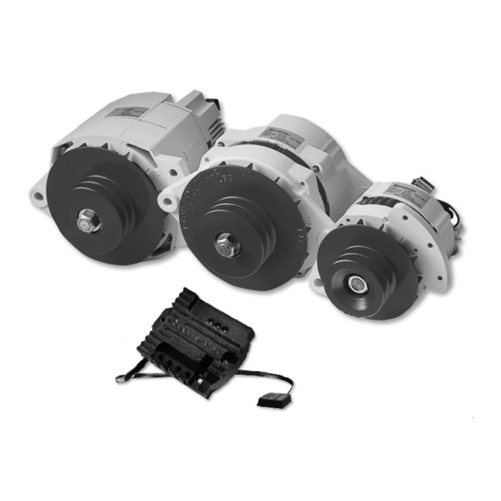
ALPHA ALTERNATOR
12/90, 12/130, 24/75, 24/95C, 24/110 & 24/150
HIGH OUTPUT ALTERNATORS WITH 3-STAGE REGULATOR
MASTERVOLT
Snijdersbergweg 93,
1105 AN Amsterdam
The Netherlands
Tel.: +31-20-3422100
Fax.: +31-20-6971006
www.mastervolt.com
ENGLISH:
NEDERLANDS:
DEUTSCH:
FRANÇAIS:
v 1.2. June 2007
PAGE 1
PAGINA 25
SEITE 49
PAGINA 73
Advertisement
Table of Contents


Need help?
Do you have a question about the Alpha 12/90 and is the answer not in the manual?
Questions and answers